Film riding pressure actuated leaf seal assembly

a technology of leaf seals and pressure actuators, applied in the direction of engine seals, climate sustainability, sustainable transportation, etc., can solve the problems of brush seals, lack of maximizing machine performance, and lack of spherical seals,

Active Publication Date: 2013-07-02
CMG TECH
View PDF25 Cites 31 Cited by
  • Summary
  • Abstract
  • Description
  • Claims
  • Application Information

AI Technical Summary

Benefits of technology

[0013]In accordance with embodiments of this invention, a pressure actuated leaf seal assembly is provided that includes film riding, hydrodynamic / hydrostatic runners under seal member leaf ends. Leaf seal assemblies according to embodiments of this invention maintain the runner away from a rotating body until adequate rotating speed and differential pressure is present to generate lift required to allow the runner to float on a thin film of operating fluid on the rotating body, so that the runner does not rub the rotating body under transient or operating conditions. In addition, runners are attached to leaf seal members such that the runners move in a radial direction, while remaining nearly parallel to the rotating body. In one embodiment, a runner can comprise a separate structure coupled to a leaf seal member, and in another embodiment, a runner can comprise a wear-resistant pad on a distal end of a leaf seal member.

Problems solved by technology

Labyrinth seals, therefore, do not maximize machine performance.
Brush seals, however, pose a number of deficiencies.
First, the multistep brush seal manufacturing process is costly.
Second, brush seal bristles do not always maintain a close running clearance because of their inherent inability to withstand long term wear.
Third, brush seals exposed to solid particles are subject to erosion or other deterioration.
Finally, brush seals are also subject to vibration due to movement of the pressurized fluid being sealed.
Therefore, brush seals oftentimes require dampening features.
A particular deficiency in these designs is initial contact of the hydrodynamic shoes with the shaft until sufficient rotor speed is achieved during startup to produce the requisite film thickness to lift the shoes from rubbing contact with the shaft.
For instance, each stacked lamination is a complete ring (not segmented) and, therefore, is limited in application to machines that require installation / replacement of seals with the rotor removed from the unit.
In addition to the above-identified problems, brush seals and finger seals operating at close running clearance are subject to rubbing and wear when differential thermal expansion of stator and rotor components eliminates clearance altogether.
For example, during a turbine shutdown, the stator component, in which a seal assembly is mounted, may cool more quickly than the rotor, causing the seal assembly to close on the rotor and rub.
The force imposed during such a rub is reduced somewhat with the flexure of brush and finger seal members, but sliding friction nevertheless causes wear and reduces the life of such seals.
High rotor speed and engine temperature during take-off increases the diameter of rotor seal surfaces, closing seal clearance and raises the opportunity for rubbing and wear.

Method used


Image

  • Film riding pressure actuated leaf seal assembly
  • Film riding pressure actuated leaf seal assembly
  • Film riding pressure actuated leaf seal assembly

Examples


Embodiment Construction

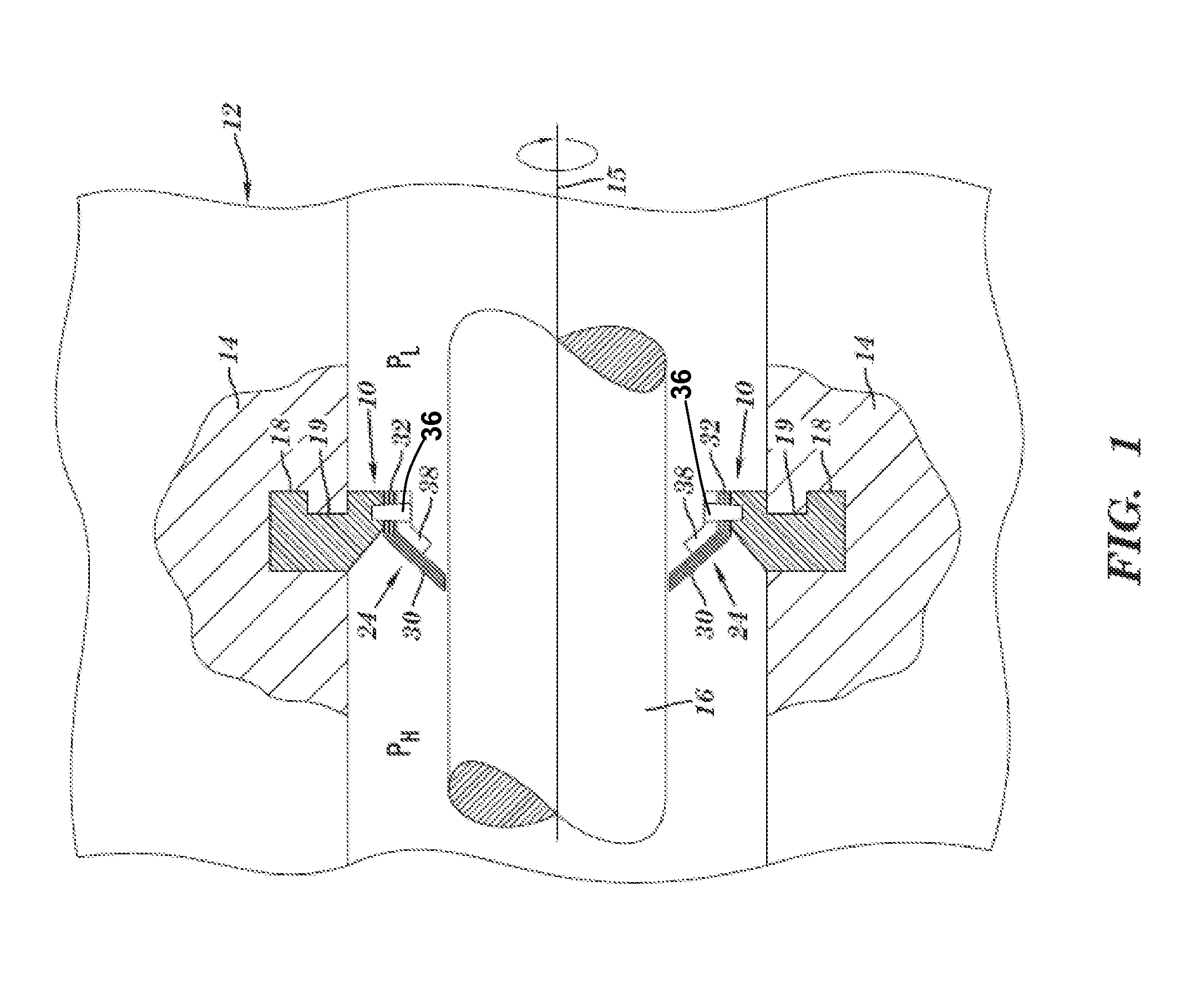
[0032]Referring to FIG. 1, a leaf seal assembly 10 for use with a rotary machine 12 including a plurality of leaf seal members 24 is shown. Leaf seal assembly 10 can be an assembly as disclosed in U.S. Pat. No. 7,578,509, which is incorporated by reference herein. Rotary machine 12 may be any well known machinery that includes a non-rotating component 14 and a rotating component 16 having a longitudinal axis 15, e.g., a centrifugal compressor, a pump or a steam turbine, etc. For description purposes, embodiments of the present invention will be described in terms of a centrifugal compressor or steam turbine having a stationary body or stator, 14 and a rotating component, or rotor, 16. As shown in FIG. 1, a higher pressure chamber PH and a lower pressure chamber PL are generated during steady state operation of rotary machine 12. Operating fluid of the turbine flows through the machine from a high pressure area PH to a lower pressure area PL. Pressure from higher pressure area PH is ...


PUM


Abstract

In accordance with embodiments of this invention, a pressure actuated leaf seal assembly is provided that includes film riding, hydrodynamic / hydrostatic runners under seal member leaf ends. Leaf seal assemblies according to embodiments of this invention maintain the runner away from a rotating body until adequate rotating speed is present to generate lift required to allow the runner to float on a thin film of operating fluid on the rotating body, so that the runner does not rub the rotating body. In addition, runners are attached, or added, to leaf seal members such that the runners move in a radial direction, while remaining parallel to the rotating body. In one embodiment, a runner can comprise a separate structure coupled to a leaf seal member, and in another embodiment, a runner can comprise a wear-resistant pad on a distal end of a leaf seal member.

Description

TECHNICAL FIELD[0001]The present invention relates generally to seals for rotary machines and, more particularly, to a film riding pressure actuated leaf seal assembly.BACKGROUND[0002]In many rotary machines, such as a multi-stage centrifugal compressor or pump, a fluid is compressed by successive stages, or in turbines, a fluid is expanded in successive stages. Both turbine and compressor stage(s) have stationary or non-rotating components, e.g., vanes, cooperating with rotating components, e.g., blades, for compressing and expanding the operational fluid. The operational fluids change in pressure through the machine and a variety of seals are provided to preserve the differential pressures where necessary to maximize machine efficiency and performance. An illustrative seal may be provided between a turbine or compressor rotor and a cooperating stator or stator body so the rotor may be pressurized to provide thrust balance relative to the rearwardly directed force generated by the ...

Claims


Application Information

Patent Timeline
Patent Type & Authority Patents(United States)
IPC IPC(8): F16J15/44F16J15/447
CPCF01D11/02F16J15/164F16J15/3292F01D11/001F16J15/445Y02T50/672F05D2240/57Y02T50/60
Inventor GRONDAHL, CLAYTON M.SMITH, RICHARD LEEDUDLEY, JAMES CARLTON
Owner CMG TECH
Why Eureka
Try Eureka