Self-sanitizing automated condensate drain cleaner and related method of use

a technology of automatic cleaning and condensate drain, which is applied in the direction of cleaning using liquids, domestic cooling devices, instruments, etc., can solve the problems of frequent clogging of condensate drains, health hazards, and failure of air conditioning systems, and achieve the effect of reducing sludge and other pathogens

Active Publication Date: 2013-07-02
PLEXAIRE
View PDF18 Cites 7 Cited by
  • Summary
  • Abstract
  • Description
  • Claims
  • Application Information

AI Technical Summary

Problems solved by technology

One of the more common problems with centralized air conditioners is the frequent clogging of condensate drains.
This build up creates not only a health hazard but also may cause the air conditioning system to malfunction and fail.
Accumulation of debris within condensate drains is known to cause colds, increase risk of asthma, cause fatigue, increased allergies, and even risk of Legionnaire's disease (Legionella bacteria).
The result is a temporary loss of air conditioning and a risk of mold growth within the home, as well as the costs associated with hiring the service technician.
Moreover, removing an obstruction within a condensate drain through manual effort fails to prevent future clogs.
The result is routine manual maintenance of these condensate drains, which typically requires spending hundreds of dollars every year on hiring service technicians.
The location and positioning of these condensate drains based upon modern construction standards only further complicates these issues.
This makes it difficult if not impossible to replace these condensate drains.
One of the several drawbacks of employing these strong chemicals is two-fold.
First, the chemicals create a large safety hazard.
For example, BenzylAmmonium Chloride is a corrosive on the MSDS and can cause shortness of breath and a burning sensation in the throat.
Long term exposure can cause coughing or wheezing.
A second limitation is that as a corrosive BenzylAmmonium Chloride can actually degrade and eat through the walls of the condensate drain after prolonged use.
This in turn would limit the longevity of the condensate drain and require a full replacement (which may be difficult due to positioning within load bearing walls).

Method used


Image

  • Self-sanitizing automated condensate drain cleaner and related method of use
  • Self-sanitizing automated condensate drain cleaner and related method of use
  • Self-sanitizing automated condensate drain cleaner and related method of use

Examples


Embodiment Construction

[0020]The present invention will now be described more fully hereinafter with reference to the accompanying drawings, in which preferred embodiments of the invention are shown. This invention may, however, be embodied in many different forms and should not be construed as limited to the embodiments set forth herein. Rather, these embodiments are provided so that this disclosure will be thorough and complete, and will fully convey the scope of the invention to those skilled in the art. Like numbers refer to like elements throughout.

Overall Positioning and Location of System

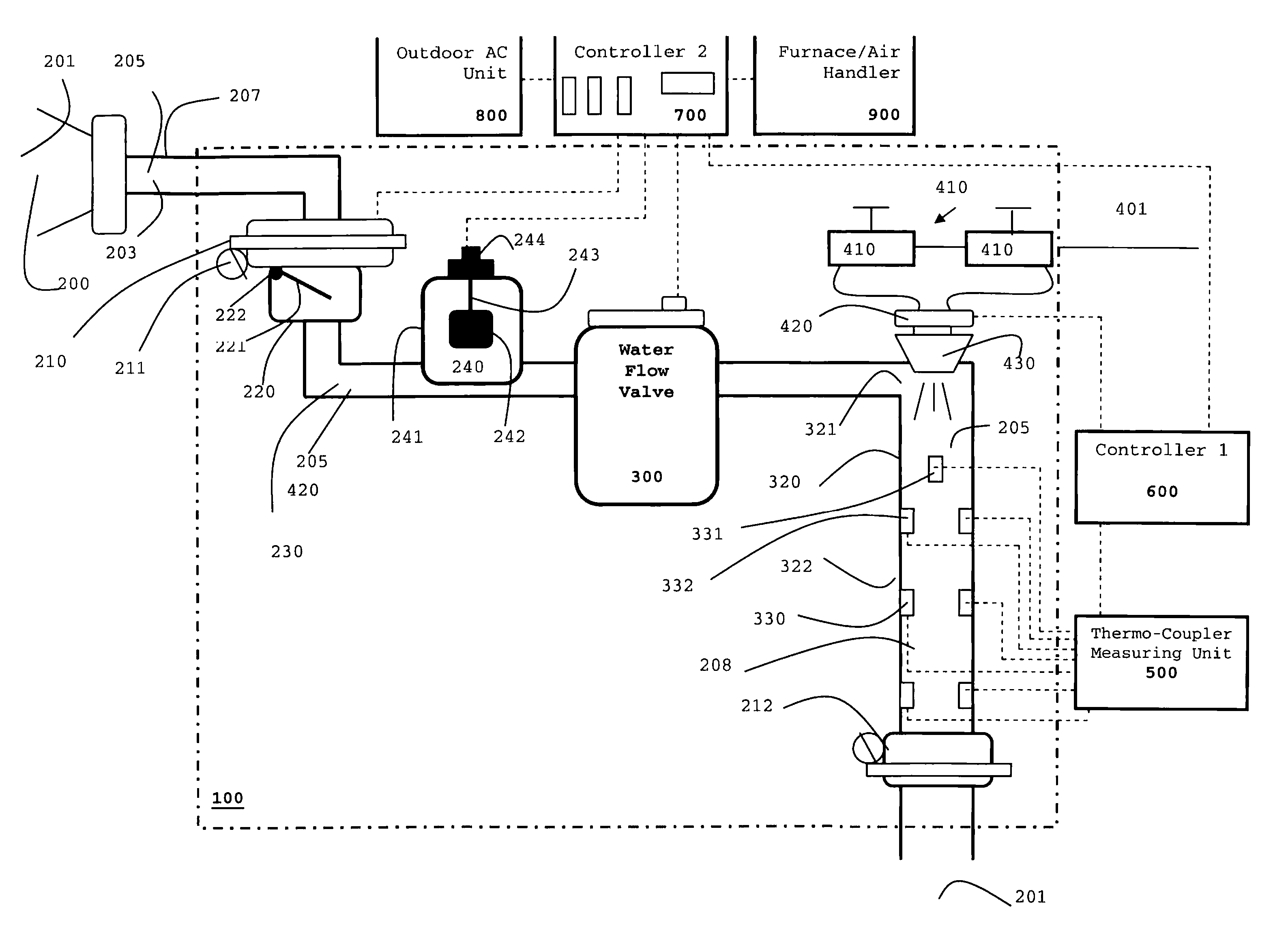
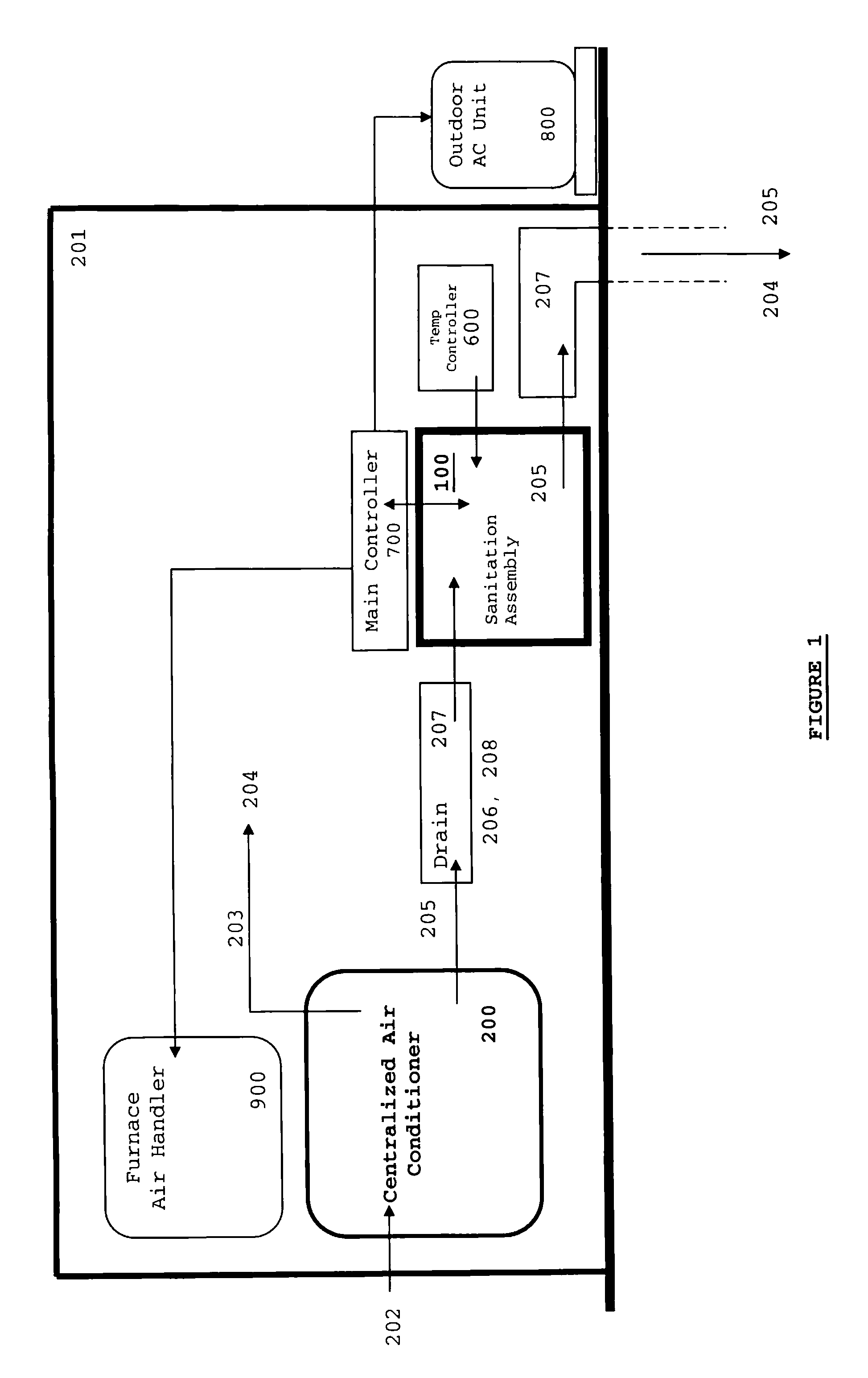
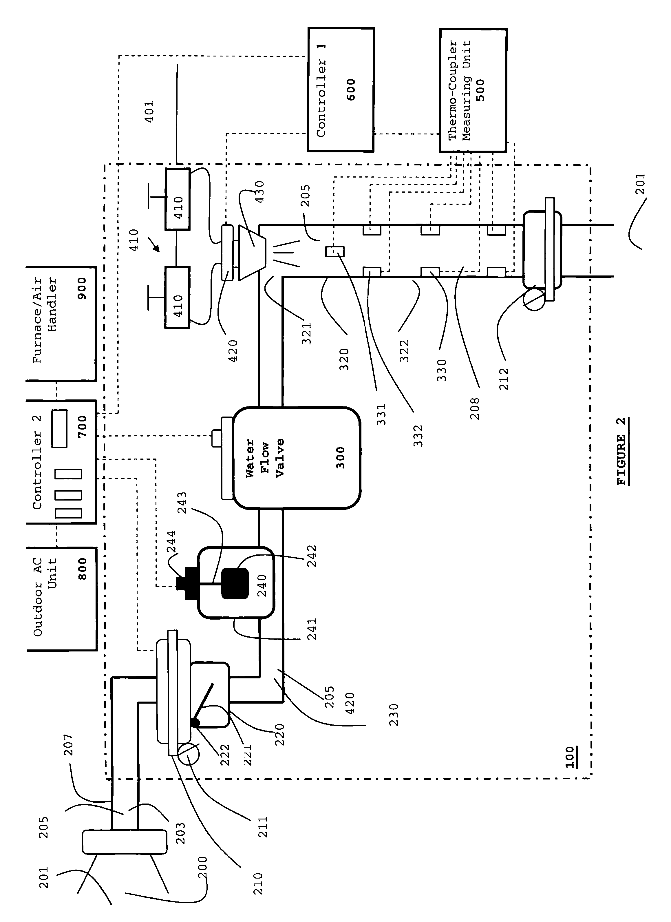
[0021]FIG. 1 illustrates, by way of example, one preferred positioning and location of a sanitation assembly 100. As shown, most residential and / or commercial facilities 201 (especially those located in sub-tropical and / or warm climates) include a centralized air conditioner system 200 (hererinafter an “air conditioner”). The air conditioner 200 takes in warm moist air 202 from outside of the facility 201 and then ...


PUM


Abstract

The invention is directed toward a system and method for sanitizing a condensate drain to reduce sludge and related pathogens. The system is directed to a sanitizing assembly having a treatment chamber connected to the condensate drain, where the treatment chamber includes a top end and a shaft. A spray assembly is positioned proximate to the top end of the treatment chamber. This spray assembly has a nozzle spray connected to a hot water source. A spray controller within the spray assembly helps disperse a sufficient quantity and pressure of hot water within the shaft to dislodge sludge, when necessary.

Description

FIELD OF THE INVENTION[0001]This invention is directed toward a system for self-cleaning condensate drains through an automated high temperature and pressure nozzle spray. More specifically, the invention relates to a plurality of thermocouples which line the condensate drain which, upon detecting a coating of sludge, activates a high temperature and pressure water supply to unclog the condensate drain.BACKGROUND OF THE INVENTION[0002]Apart from cooling air for circulation within a home or commercial facility, centralized air conditioners also produce condensate as a byproduct. Such condensate is created from the cooling of humid air, typically drawn from outside of the home or facility, upon treatment by the central air conditioner. Most modern central air conditioning systems include a condensate drain which collects this byproduct for removal outside of the home or facility. Such condensate drains often include a drain line which creates a conduit for removing condensate byproduc...

Claims


Application Information

Patent Timeline
Patent Type & Authority Patents(United States)
IPC IPC(8): B08B9/027
CPCB08B9/027F24F13/222B08B9/0325F24F2013/227F24F2013/228Y10T137/0424
Inventor KAISER, STEWART
Owner PLEXAIRE
Why Eureka
Try Eureka