Interface for MEMS inertial sensors

a technology of inertial sensor and interface, which is applied in the direction of pulse manipulation, pulse technique, instruments, etc., can solve the problems of severe degradation of the performance of the detection front-end circuit, undesired coupling that can occur, and insufficiently satisfying existing interface techniques in various respects

Active Publication Date: 2013-07-02
SHENZHEN GOODIX TECH CO LTD +1
View PDF2 Cites 35 Cited by
  • Summary
  • Abstract
  • Description
  • Claims
  • Application Information

AI Technical Summary

Benefits of technology

[0027]This patent disclosure describes an ASIC or other circuit to interface with MEMS inertial sensors such as vibratory MEMS gyroscopes and accelerometers, including in closed loop configurations. Closed loop configuration provides best performance in harsh environments. Techniques to improve the sensor interface performance are described, including techniques that allow for extending dynamic range of the MEMS actuation and detection signals, canceling coupling between electrodes in the MEMS module, and achieving fine phase tuning between sense and drive loops for improved demodulation.

Problems solved by technology

Existing interface techniques are not fully satisfactory in various respects.
Another issue relates to undesired coupling that can occur between the actuation stream of one channel and detection paths of the same channel, or even different channels (e.g., sense mode to sense mode coupling or sense mode to drive mode coupling, etc.).
Such coupling can distort the signal and result in severe degradation in the performance of the detection front-end circuits.
Various approaches to achieving this phase adjustment typically entail power and / or area penalties.

Method used


Image

  • Interface for MEMS inertial sensors
  • Interface for MEMS inertial sensors
  • Interface for MEMS inertial sensors

Examples


Embodiment Construction

[0026]Summary

[0027]This patent disclosure describes an ASIC or other circuit to interface with MEMS inertial sensors such as vibratory MEMS gyroscopes and accelerometers, including in closed loop configurations. Closed loop configuration provides best performance in harsh environments. Techniques to improve the sensor interface performance are described, including techniques that allow for extending dynamic range of the MEMS actuation and detection signals, canceling coupling between electrodes in the MEMS module, and achieving fine phase tuning between sense and drive loops for improved demodulation.

[0028]Description

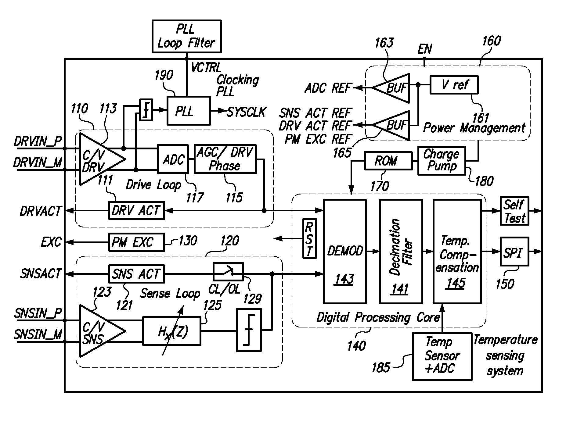
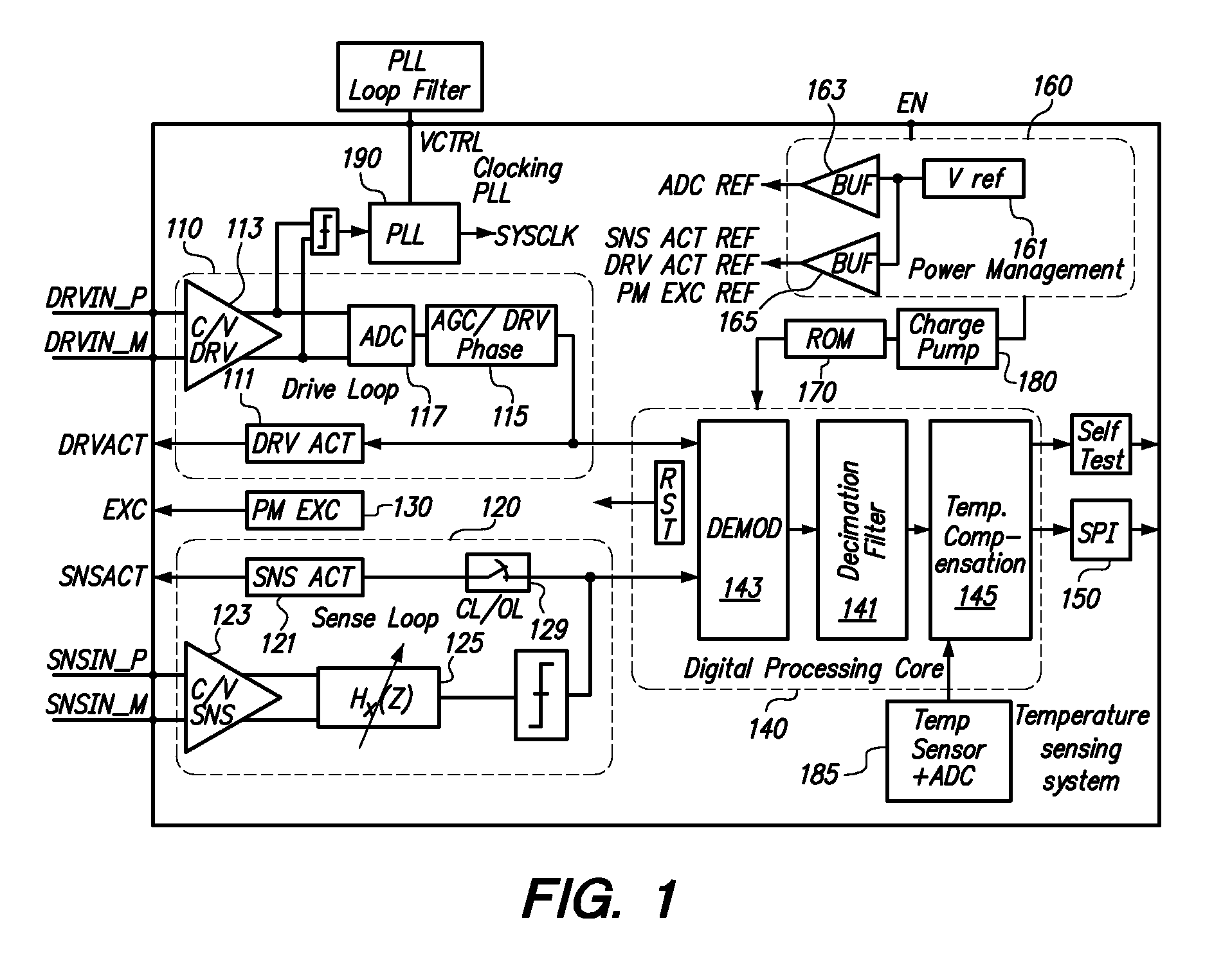
[0029]The system architecture of an exemplary ASIC is shown in FIG. 1. Functionally, this system can be divided into main blocks as follows:

[0030]1—MEMS Sensor Interface Circuitry (110, 120, 130):

[0031]This part of the circuit provides actuation voltages for sense and drive electrodes of the MEMS sensor, through sense actuation (SNS ACT) switches 121 and drive actuation...


PUM


Abstract

In a high-performance interface circuit for micro-electromechanical (MEMS) inertial sensors, an excitation signal (used to detect capacitance variation) is used to control the value of an actuation signal bit stream to allow the dynamic range of both actuation and detection paths to be maximized and to prevent folding of high frequency components of the actuation bit stream due to mixing with the excitation signal. In another aspect, the effects of coupling between actuation signals and detection signals may be overcome by performing a disable / reset of at least one of and preferably both of the detection circuitry and the MEMS detection electrodes during actuation signal transitions. In a still further aspect, to get a demodulated signal to have a low DC component, fine phase adjustment may be achieved by configuring filters within the sense and drive paths to have slightly different center frequencies and hence slightly different delays.

Description

RELATED APPLICATIONS[0001]This application claims benefit of U.S. Application 61 / 382,898 titled SELF-CLOCKED ASIC INTERFACE FOR MEMS INERTIAL SENSORS filed 14 Sep. 2010, incorporated herein by reference.BACKGROUND OF THE INVENTION[0002]Numerous applications of micro-electromechanical (MEMS) inertial sensors require a high-performance ASIC interface. Existing interface techniques are not fully satisfactory in various respects.[0003]For example, in feedback (e.g., force-feedback) systems where a drive loop is present, an excitation signal is needed for detection of capacitance variations in both a sense loop and a drive loop. The excitation signal should not affect the actuation applied, for example, to a proof mass (or proof masses) of the MEMS sensor. However, since the excitation signal is applied to the proof mass, and since actuation capacitors share the same proof mass with the detection capacitors, therefore the excitation signal affects the actuation signal content and dynamic...

Claims


Application Information

Patent Timeline
Patent Type & Authority Patents(United States)
IPC IPC(8): H03B1/00H03K5/00H04B1/10
CPCG01C19/5776G01P15/125
Inventor MOKHTAR, AHMEDELMALLAH, AHMEDELSHENNAWY, AHMEDSHABAN, AHMEDGEORGE, BOTROSELMALA, MOSTAFAISMAIL, AYMANSAKR, MOSTAFAELSAYED, AYMAN
Owner SHENZHEN GOODIX TECH CO LTD
Why Eureka
Try Eureka