Broadband antenna system for satellite communication

a satellite communication and antenna system technology, applied in the direction of antenna arrays, basic electric elements, electric devices, etc., can solve the problems of extreme requirements, lack of suitable antennas, directional, wire-free data communication with satellites,

Active Publication Date: 2013-07-02
QEST QUANTENELEKTRONISCHE SYST TUBINGEN GMBH
View PDF11 Cites 33 Cited by
  • Summary
  • Abstract
  • Description
  • Claims
  • Application Information

AI Technical Summary

Benefits of technology

[0019]The object of the invention is to provide a broadband antenna system, in particular for aeronautical applications, which, with minimal dimensions, allows transmission operation and reception operation in compliance with the regulations, and allows the antenna to be aligned precisely with the target satellite.

Problems solved by technology

However, particularly in the aeronautical field, there is a lack of suitable antennas which, in particular, can satisfy the conditions required for mobile use, such as small dimensions and light weight.
Furthermore, directional, wire-free data communication with satellites (for example in the Ku or Ka band) is subject to extreme requirements for the transmission characteristic of the antenna systems, since interference of adjacent satellites must be reliably precluded.
In aeronautical applications, the weight and the size of the antenna system are of very major importance, since they reduce the payload of the aircraft, and cause additional operating costs.
The problem is therefore to provide antenna systems which are as small and light as possible and which nevertheless comply with the regulatory requirements for transmission and reception operation when used on mobile carriers.
This leads to stringent requirements for the angle-dependent antenna characteristic.
However, antennas such as these are unsuitable for mobile use, in particular on aircraft.
However, antenna arrays are subject to the known problem of so-called grating lobes.
At certain beam angles, this leads to positive interference between the antenna elements, and therefore to undesirable emission of electromagnetic power in undesired solid angle ranges.
Since antenna arrays must have a feed network, this results in the practical problem of finding network and antenna array topologies which, on the one hand, satisfy the above condition for the maximum distance between the beam centers, and on the other hand occupy as little physical space as possible.
This so-called geographic skew cannot be compensated for in mobile applications by rotation of the antenna about an axis at right angles to the aperture plane, as is possible with stationary terrestrial antennas.
Despite the aspect ratio, which is in principle poor, an aeronautical antenna system must therefore be able to comply with the regulatory requirements even in the presence of a geographic skew, up to a specific rotation angle of typically about ±35°.
The very high polarization decoupling which is required for operation as a transmitting antenna cannot be achieved with the proposed network of square waveguides.
However, transmission operation that is permitted in accordance with the regulations is impossible since, for example, CFR 25.209 and CFR 25.222 place very stringent requirements on sidelobe suppression.
This greatly restricts the usable bandwidth.
By virtue of the design, the antenna element centers are, however, a comparatively long distance apart from one another, as a result of which parasitic sidelobes occur.
The same problem occurs with the arrangements proposed, for example, in U.S. Pat. No. 6,225,960, International Publication No.
However, by virtue of the design, the beam centers are also far more than one wavelength apart from one another in this case as well, and parasitic sidelobes, which are dependent on the phase correlation, still occur.

Method used


Image

  • Broadband antenna system for satellite communication
  • Broadband antenna system for satellite communication
  • Broadband antenna system for satellite communication

Examples


Embodiment Construction

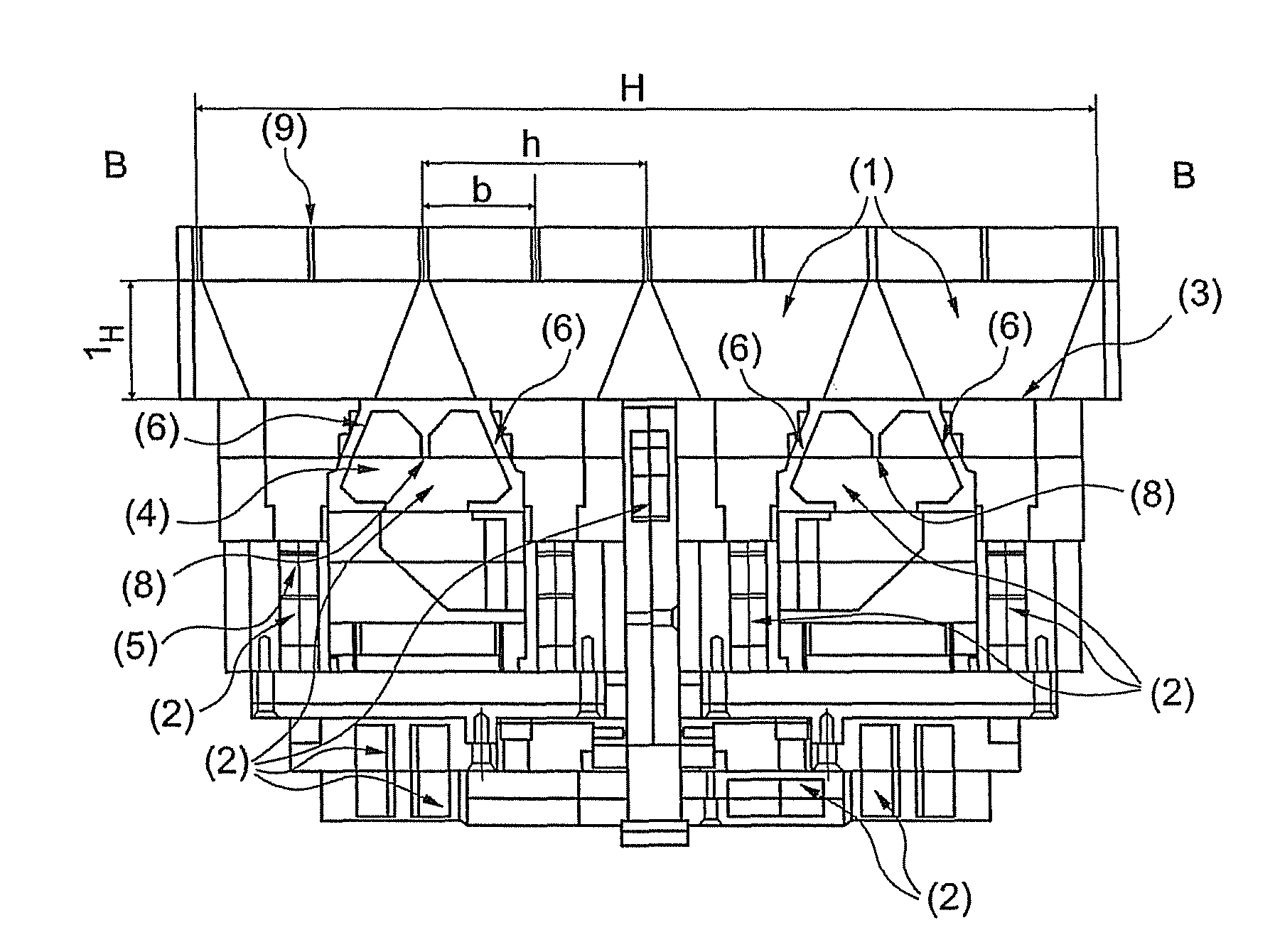
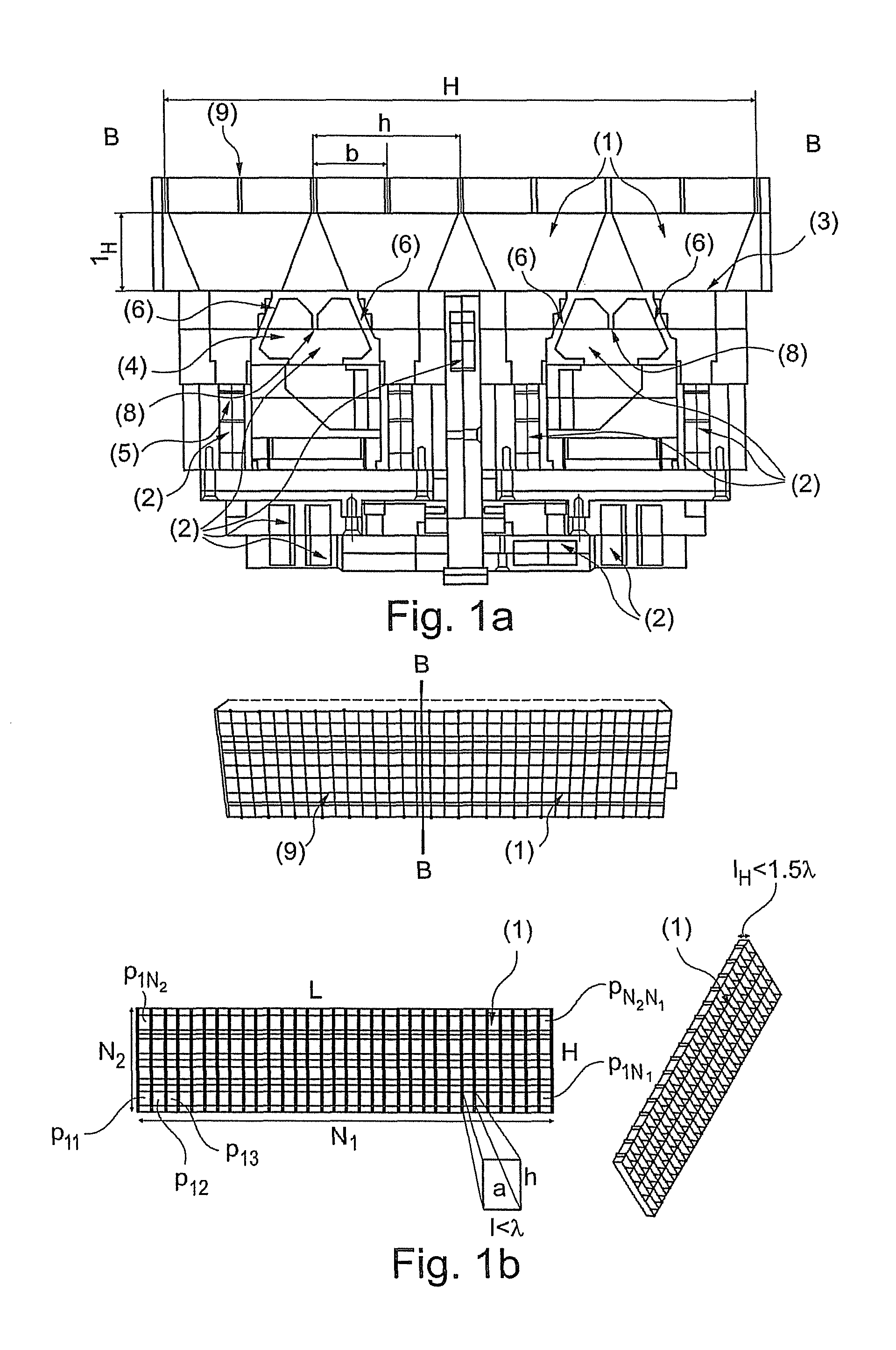
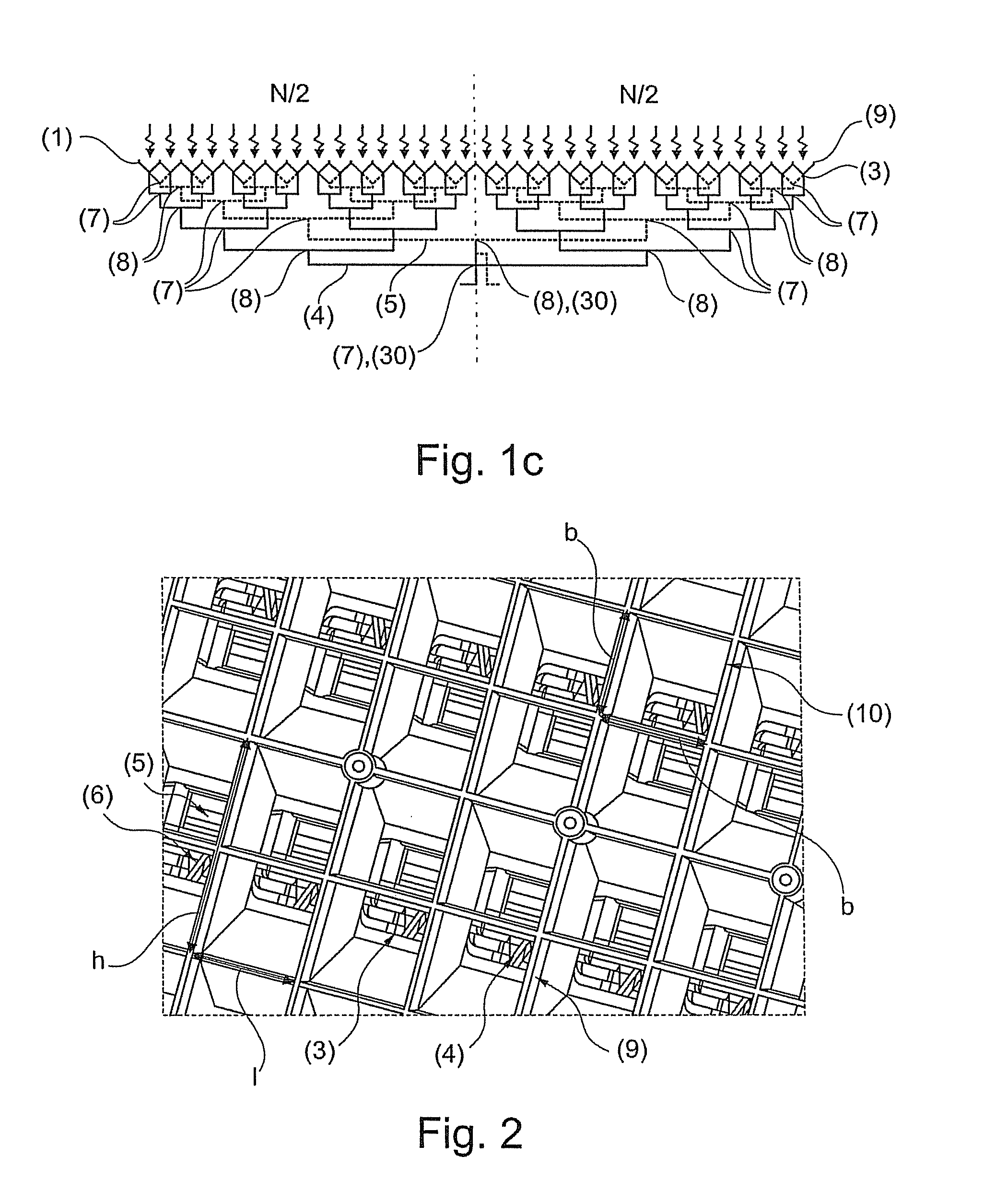
[0029]FIGS. 1a-c illustrate one preferred design of the antenna system according to the invention. The antenna for broadband satellite communication, in particular for mobile applications, consists of an array of primary horn antenna elements (1) which are connected to one another by a waveguide feed network (2), wherein the antenna consists of a number N=N1×N2 of primary horn antenna elements where N1>4 N2, N1 and N2 are even integers, the total aperture area A of the antenna is A=L×H, where L≧4 H and L1λ, where λ is the minimum free-space wavelength of the electromagnetic wave to be transmitted or to be received, the primary horn antenna elements allow the reception and the transmission of two orthogonal linear-polarized electromagnetic waves in that they have a rectangular aperture area a=l×h where l3), where L=N1 l, H=N2 h and A=N1×N2×l×h=L×H, and the primary horn antenna elements (1) are fed directly at their output (3) via rectangular waveguides (4, 5) such that one of the ort...


PUM


Abstract

An antenna for broadband satellite communication including an array of primary horn antenna elements which are connected to one another by a waveguide feed network.

Description

CROSS REFERENCE TO RELATED APPLICATIONS[0001]This application is a continuation of International Application No. PCT / EP2010 / 002645 filed Apr. 30, 2010, which designated the United States, and claims the benefit under 35 USC §119(a)-(d) of German Application No. 10 2009 019 291.3 filed Apr. 30, 2009, the entireties of which are incorporated herein by reference.FIELD OF THE INVENTION[0002]The invention relates to a broadband antenna system for communication between mobile carriers and satellites, in particular for aeronautical applications.BACKGROUND OF THE INVENTION[0003]The need for wire-free broadband channels for data transmission at very high data rates, particularly in the field of mobile satellite communication, is increasing continuously. However, particularly in the aeronautical field, there is a lack of suitable antennas which, in particular, can satisfy the conditions required for mobile use, such as small dimensions and light weight. Furthermore, directional, wire-free dat...

Claims


Application Information

Patent Timeline
Patent Type & Authority Patents(United States)
IPC IPC(8): H01Q13/00
CPCH01Q21/064H01Q13/0258
Inventor SEIFRIED, MICHAELWENZEL, MICHAELHAUSSLER, CHRISTOPHOPPENLANDER, JORGTOMES, JORGFRIESCH, ALEXANDER
Owner QEST QUANTENELEKTRONISCHE SYST TUBINGEN GMBH
Why Eureka
Try Eureka