Hydraulic valve device

a technology of valve body and valve valve body, which is applied in the direction of diaphragm valve, servomotor, engine diaphragm, etc., to achieve the effect of better managemen

Inactive Publication Date: 2013-07-09
HYDAC FILTERTECHNIK GMBH
View PDF16 Cites 2 Cited by
  • Summary
  • Abstract
  • Description
  • Claims
  • Application Information

AI Technical Summary

Benefits of technology

[0004]An object of the invention is to provide improved the valve solutions such that system vibrations in the load sensing contro

Problems solved by technology

This coaxial arrangement of the valve spool and pressure compensator is e

Method used


Image

  • Hydraulic valve device
  • Hydraulic valve device
  • Hydraulic valve device

Examples


Embodiment Construction

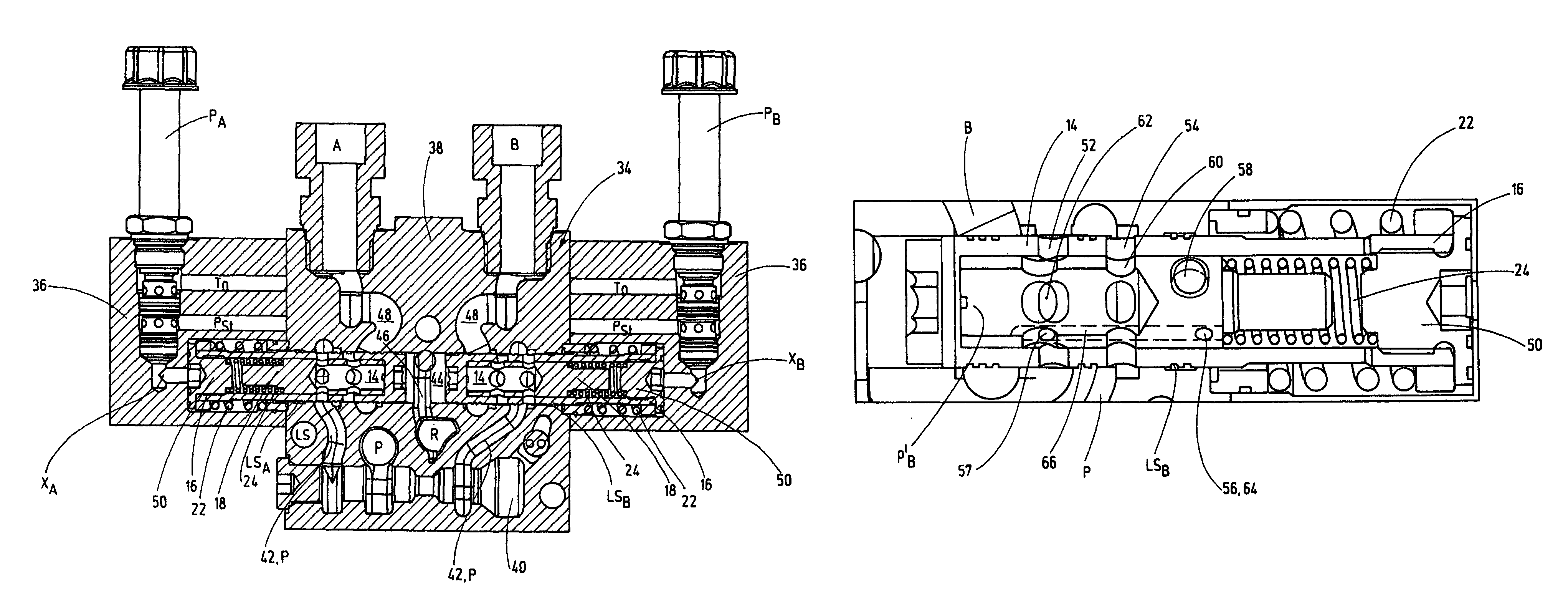
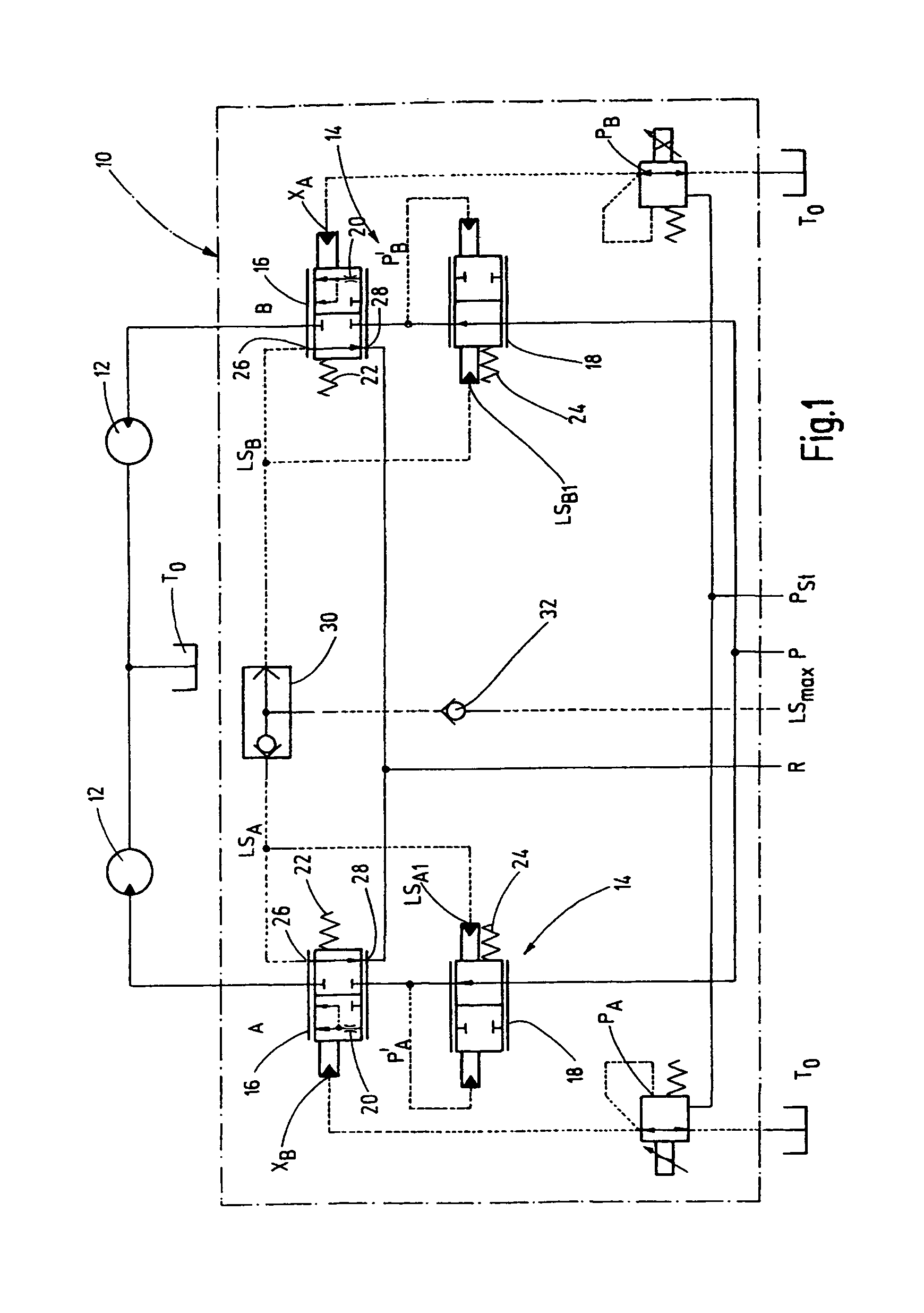
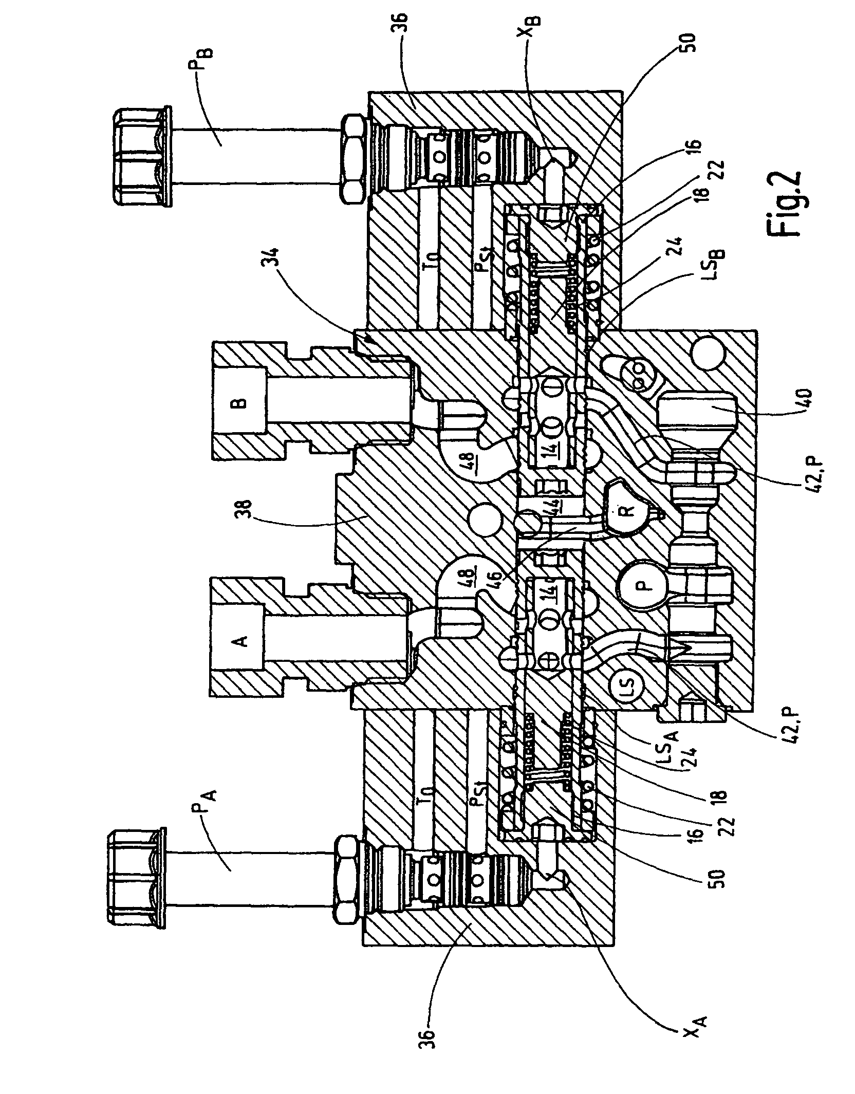
[0014]The hydraulic valve device as shown in FIG. 1 has a fluid connector arrangement 10, containing a pressure supply connector P, a return flow connector R, a section load sensing connector LS with LSmax, two control connectors P′A, P′B, two utility connectors A, B, and two hydraulic motors 12. Motors 12 are independent of one another, are connected to the utility connectors A, B as consumers and are connected to a common tank connector T0. The hydraulic valve device also has two controls 14 for at least partial triggering of the connectors of the fluid connector arrangement 10. The respective control 14 has, assigned to each utility connector A, B, a valve spool 16 to which a pressure compensator 18 is connected upstream. The valve spool 16 and pressure compensator 18 are built in the form of proportional valves, the respective valve spool 16 being provided with a throttle or orifice 20. Both the pressure compensator 18 and the valve spool 16, as shown in FIG. 1, are held spring-...


PUM


Abstract

A hydraulic valve device, especially an LS current regulating valve, includes a fluid connection arrangement (10). As the respective control device (14) associated with a useful connection (A) comprises a control slide (16) upstream of which a pressure balance (18) is mounted in the fluid direction towards each useful connection (A, B), any system vibrations occurring in the load sensing regulating circuit can be better controlled and the respectively connected hydraulic consumer can be subjected to a constant current regulation.

Description

FIELD OF THE INVENTION[0001]The invention relates to a hydraulic valve device, in particular a LS flow control valve, with a fluid connector arrangement containing at least a pressure supply connector (P), a return flow connector (R), a section load sensing connector (LS), two control connectors (P′A) and (P′B), two utility connectors (A, B) and at least one displaceable control for at least partially triggering connectors of the fluid connector arrangement.BACKGROUND OF THE INVENTION[0002]DE 10 2005 033 222 A1 discloses a LUDV valve arrangement in which a control valve forms an inlet metering orifice to which an individual pressure compensator is connected downstream. By the LUDV valve arrangement, a hydraulic consumer connected to two consumer connectors of the control arrangement is triggered. To set a quick traverse, two pressure spaces of the consumer can be connected to one another and to a source of hydraulic fluid. To prevent sagging of the consumer pressure, this connection...

Claims


Application Information

Patent Timeline
IPC IPC(8): F15B13/043
CPCF15B13/0402F15B13/08F15B13/0418Y10T137/87209Y10T137/877
Inventor RUB, WINFRIED
Owner HYDAC FILTERTECHNIK GMBH
Why Eureka
Try Eureka