Multibaseline PRF-shift magnetic resonance thermometry

a magnetic resonance and multi-baseline technology, applied in the field of magnetic resonance thermometry, can solve the problems of inaccurate temperature estimates, sensitive to rapid anatomical phase variations, and erroneous baseline phase subtraction

Active Publication Date: 2013-07-09
INSIGHTEC +1
View PDF29 Cites 31 Cited by
  • Summary
  • Abstract
  • Description
  • Claims
  • Application Information

AI Technical Summary

Benefits of technology

[0011]Compared to pure multibaseline methods, the hybrid approach is not undermined by main-field shifts during therapy. Compared to referenceless methods, it accommodates rapidly-varying anatomical phase, and does not require the user to have a priori knowledge of a hot spot's location in order to obtain an accurate temperature map, nor does it require sophisticated tracking techniques to follow the hot spot's location during motion. Various embodiments of the present invention are therefore more accurate and less vulnerable to common error sources than conventional thermometry techniques. Further, in certain embodiments, fewer baseline images, compared to conventional multibaseline thermometry, are required to accurately estimate temperature, resulting in higher efficiency and decreased computation time requirements.
[0014]In some embodiments, the baseline image(s) are registered to the treatment image and transformed into corresponding adjusted baseline images based on the registration, and the phase background is subsequently estimated based on the adjusted baseline image(s). The transformation may compensate for relative in-plane or out-of-plane motion of the imaging region between the baseline image(s) and the treatment image.
[0016]The residual phase may be smoothly extended into the subregion by regression (e.g., least-square regression) after removal of pixels corresponding to the subregion from an image of the residual phase. Alternatively, in some embodiments, the residual phase is smoothly extended into the subregion by a regression method that does not require removal of pixels corresponding to the subregion from an image of the residual phase, e.g., an iterative reweighted L1 regression. Further, in some embodiments, smoothly extending the residual phase into the subregion includes computing finite differences between neighboring pixels in an image of the residual phase to determine a residual phase derivative, smoothly extending the residual phase derivative into the subregion, and then integrating the smoothly extended residual phase derivative to obtain the smoothly extended residual phase.

Problems solved by technology

This technique is, however, very sensitive to motion between the baseline images and images acquired during heating because motion causes misregistration between the images, resulting in erroneous baseline phase subtraction and inaccurate temperature estimates.
While referenceless methods are immune to motion, they are sensitive to rapid anatomical phase variations, since these cannot be accurately expressed as a weighted sum of smooth functions.

Method used


Image

  • Multibaseline PRF-shift magnetic resonance thermometry
  • Multibaseline PRF-shift magnetic resonance thermometry
  • Multibaseline PRF-shift magnetic resonance thermometry

Examples


Embodiment Construction

1. MRI System and PRF Thermometry

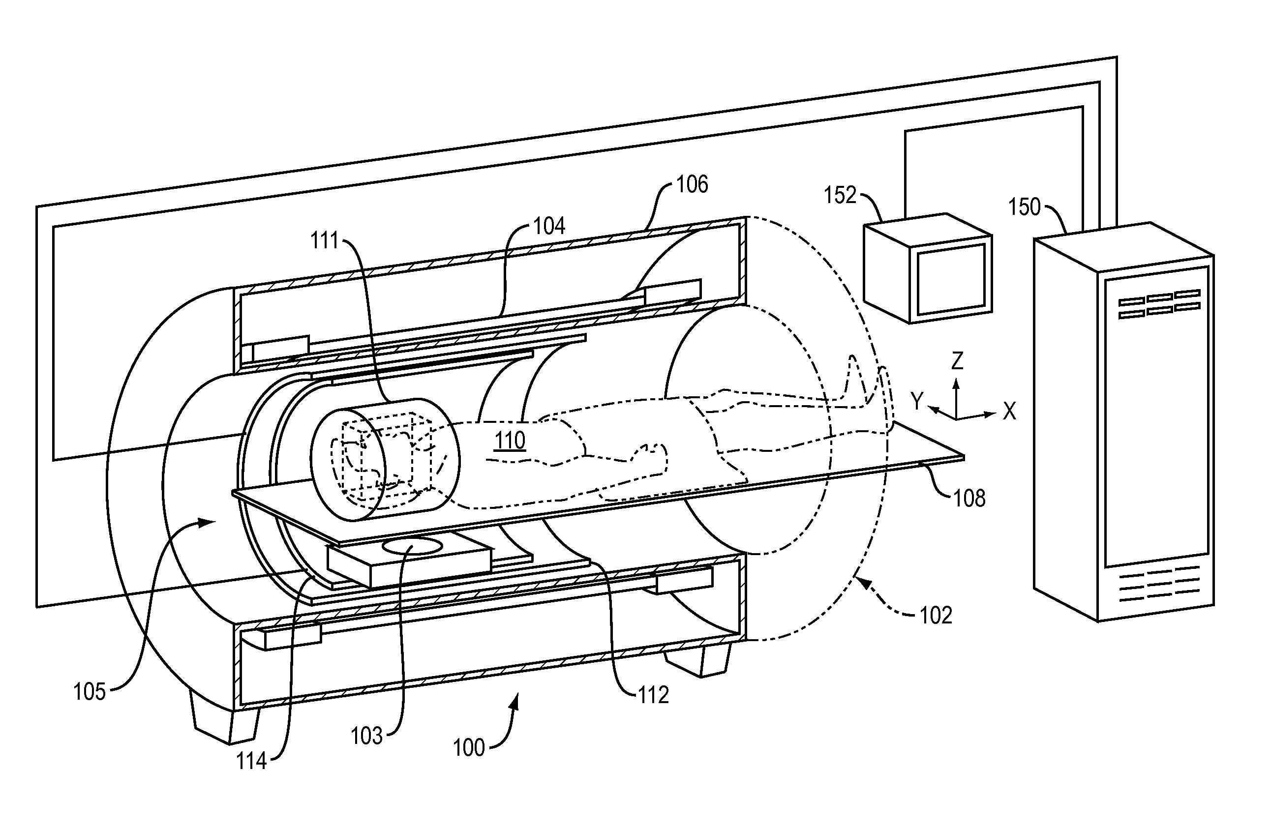
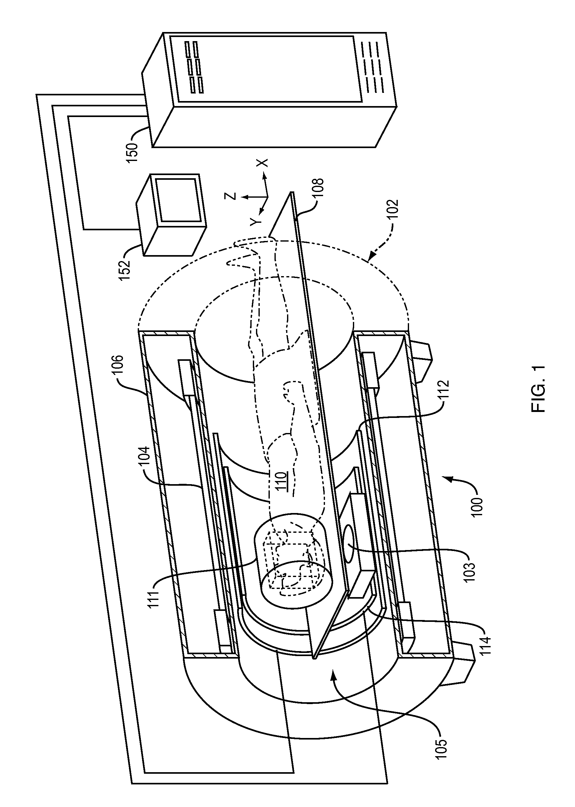
[0034]MRI systems in which the techniques described herein may be implemented are well-known in the art; an exemplary system is shown in FIG. 1. The illustrated system 100 comprises an MRI machine 102 and, when an MR-guided thermal procedure is being performed, a thermal therapy device 103 that may be disposed within the bore of the MRI machine 102. The thermal therapy device 103 may be, for example, an ultrasound transducer, an RF or microwave ablation device, a laser, or any other device adapted to heat a target tissue, and may be configured either for placement outside the patient or for insertion into the patient's body. The MRI machine 102 typically comprises a cylindrical electromagnet 104, which generates a static magnetic field within a bore 105 of the electromagnet 104. The electromagnet 104 may be enclosed in a magnet housing 106. A support table 108, upon which a patient 110 lies during treatment, is disposed within the magnet bore 105. Th...


PUM


Abstract

The phase background of a proton resonance frequency shift treatment image may be estimated by fitting a combination of baseline images to the treatment image.

Description

CROSS-REFERENCE TO RELATED APPLICATION[0001]This application claims priority to and the benefit of U.S. Provisional Patent Application No. 61 / 296,214, filed on Jan. 19, 2010, the entire disclosure of which is hereby incorporated herein by reference.STATEMENT REGARDING FEDERALLY SPONSORED RESEARCH[0002]This invention was made with government support under contracts CA121163 and EB007715 awarded by the National Institutes of Health. The government has certain rights in this invention.FIELD OF THE INVENTION[0003]The present invention relates generally to magnetic resonance (MR) thermometry during thermal treatment of internal body tissues, and in particular to phase background compensation in proton resonance frequency (PRF) shift thermometry.BACKGROUND OF THE INVENTION[0004]MR imaging of internal body tissues may be used for numerous medical procedures, including diagnosis and surgery. In general terms, MR imaging starts by placing a subject in a relatively uniform, static magnetic fi...

Claims


Application Information

Patent Timeline
Patent Type & Authority Patents(United States)
IPC IPC(8): G01V3/00
CPCG01R33/4804G01R33/56509G01R33/5611
Inventor GRISSOM, WILLIAM A.PAULY, KIM BUTTSLUSTIG, MICHAELMEDAN, YOAVLEVY, YOAVRIEKE, VIOLA
Owner INSIGHTEC
Why Eureka
Try Eureka