Power plant

a power plant and power generation technology, applied in mechanical equipment, transportation and packaging, gearing, etc., can solve the problems of inability to obtain a sufficient power generation efficiency and reduce the drive efficiency of the power plant, and achieve the effect of improving the drive efficiency and the power generation efficiency thereo

Inactive Publication Date: 2013-07-16
HONDA MOTOR CO LTD
View PDF5 Cites 5 Cited by
  • Summary
  • Abstract
  • Description
  • Claims
  • Application Information

AI Technical Summary

Benefits of technology

[0007]It is an object of the present invention to provide a power plant which is capable of improving the drive efficiency and the power generation efficiency thereof when electric power is generated using the power of a driven part thereof.
[0008]To attain the above object, the present invention provides a power plant for driving a driven part, comprising a prime mover having an output shaft, a planetary gear train including a sun gear, a ring gear, and a carrier rotatably supporting a planetary gear in mesh with the sun gear and the ring gear, the sun gear and the ring gear being connected to the driven part, the carrier being connected to the output shaft of the prime mover, a rotary motor having an output connected to one of the sun gear and the ring gear, and a transmission connected between the other of the sun gear and the ring gear, and the driven part, for varying a speed of power of the prime mover and transmitting the power to the driven part.
[0009]With the arrangement of the power plant according to the present invention, the carrier of the planetary gear train is connected to the output shaft of the prime mover, and the sun gear and the ring gear are connected to the driven part. The output of the rotary motor is connected to one of the sun gear and the ring gear (hereinafter referred to as “the one gear”), and the transmission is connected between the other of the sun gear and the ring gear (hereinafter referred to as “the other gear”) and the driven part. Thus, the rotary motor and the driven part are connected to each other not via the transmission, and hence the transmission of power between the rotary motor and the driven part can be executed without causing power transmission loss. Therefore, compared with the conventional cases where the power transmission is necessarily executed via the transmission, it is possible to increase the efficiency of driving the driven part by the rotary motor and the efficiency of electric power generation by the rotary motor using the power of the driven part.
[0010]Further, the prime mover and the driven part are connected to each other via the carrier and the one gear (hereinafter, a path formed by these component elements will be referred to as “the first power transmission path”), and via the carrier, the other gear, and the transmission (hereinafter, a path formed by these component elements will be referred to as “the second power transmission path”). Thus, as the path connecting between the prime mover and the driven part, the power plant has not only the second power transmission path including the transmission, but also the first power transmission path not including the transmission. Therefore, compared with the conventional cases where the power transmission between the prime mover and the driven part is necessarily executed via the transmission, it is possible to suppress power transmission loss at the transmission, and hence it is also possible to increase the efficiency of driving the driven part by the prime mover. Further, for the same reason, it is possible to reduce the torque transmitted to the transmission, and hence by employing a transmission adapted to the reduced transmission torque, it is possible to attain the high efficiency and reduced size of the transmission, which in turn makes it possible to attain further improvement of the drive efficiency of the power plant in its entirety, and the reduction of the size thereof.
[0013]According to this preferred embodiment, the one gear and the other gear are both connected to the drive wheels formed by one of a front set of wheels and a rear set of wheels, and hence, whichever of the output of power from the rotary motor or the electric power generation by the rotary motor may be executed during driving of the vehicle by the power of the prime mover, differently from the above-mentioned cases, the reaction forces from the road surface do not act on the front and rear drive wheels in a manner causing torque to be balanced between the front wheels and the rear wheels. Therefore, it is possible to further increase the drive efficiency of the drive wheels and easily control the torque of the drive wheels to a desired magnitude.

Problems solved by technology

As described above, in the conventional power plant, since during operation in the torque circulation mode, the transmission of power from the motor generator to the drive wheels is carried out necessarily via the stepless transmission, and hence due to power transmission loss at the stepless transmission, the drive efficiency of the power plant is reduced.
Further, for example, during the operation in the torque circulation mode, also when electric power is generated by the motor generator using the power of the drive wheels, the transmission of power from the drive wheels to the motor generator is performed via the stepless transmission, and hence it is also impossible to obtain a sufficient power generation efficiency due to power transmission loss at the stepless transmission.

Method used


Image

  • Power plant
  • Power plant
  • Power plant

Examples


Embodiment Construction

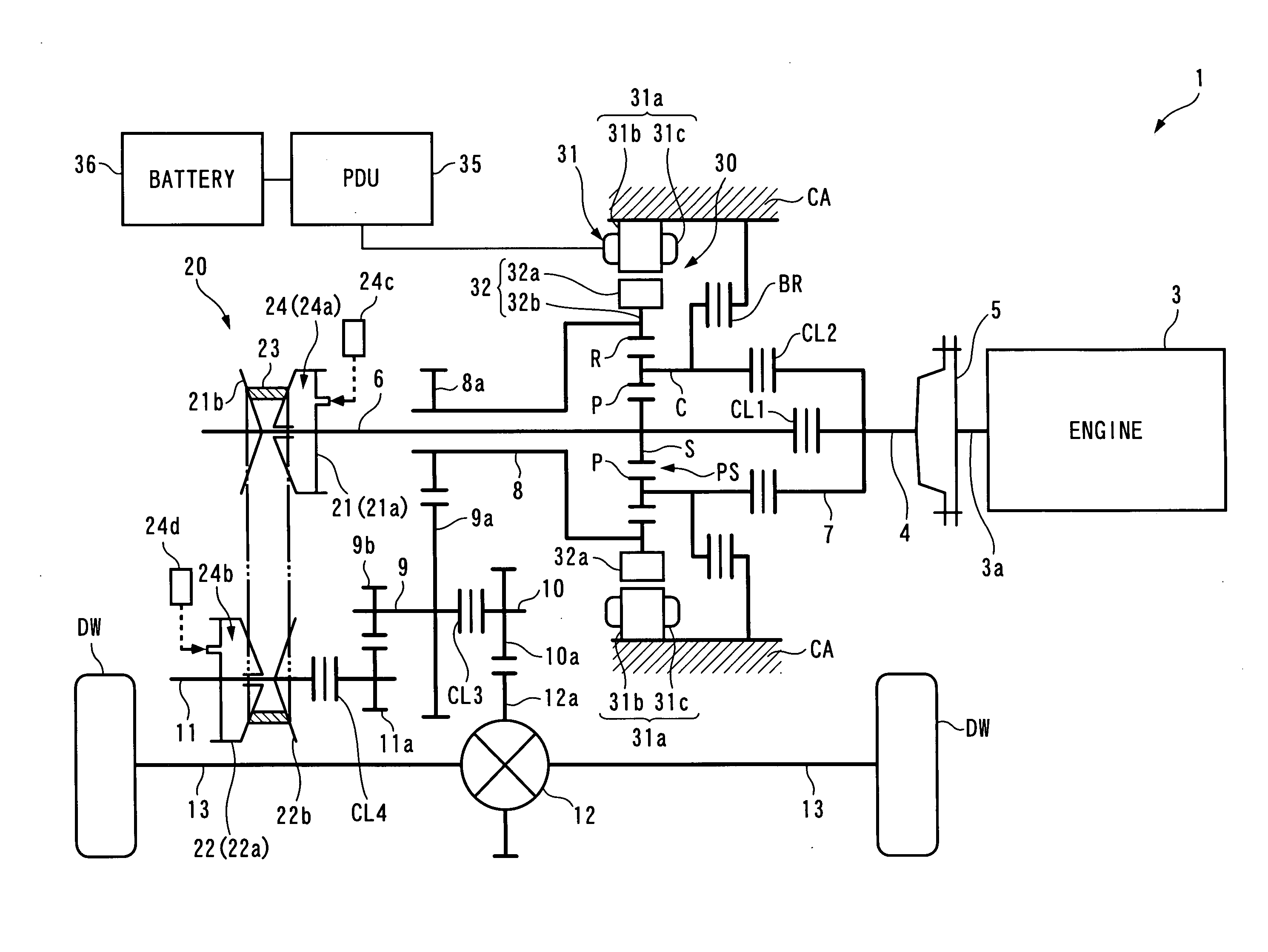
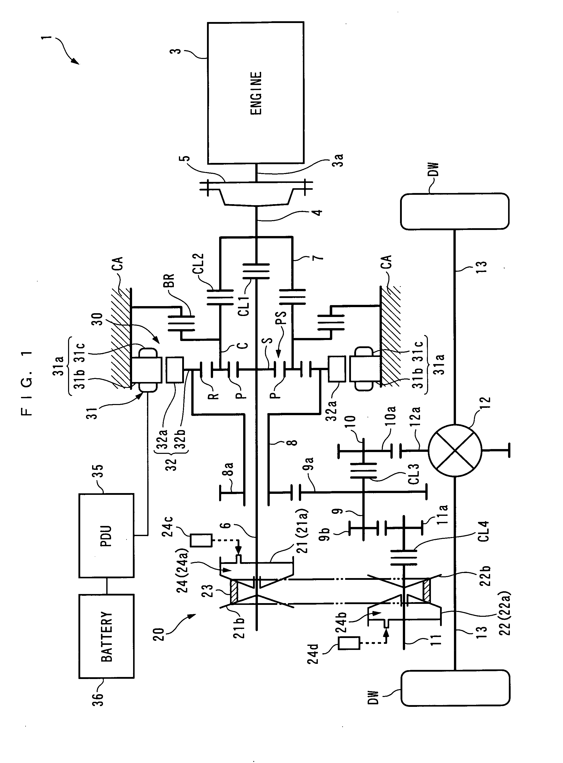
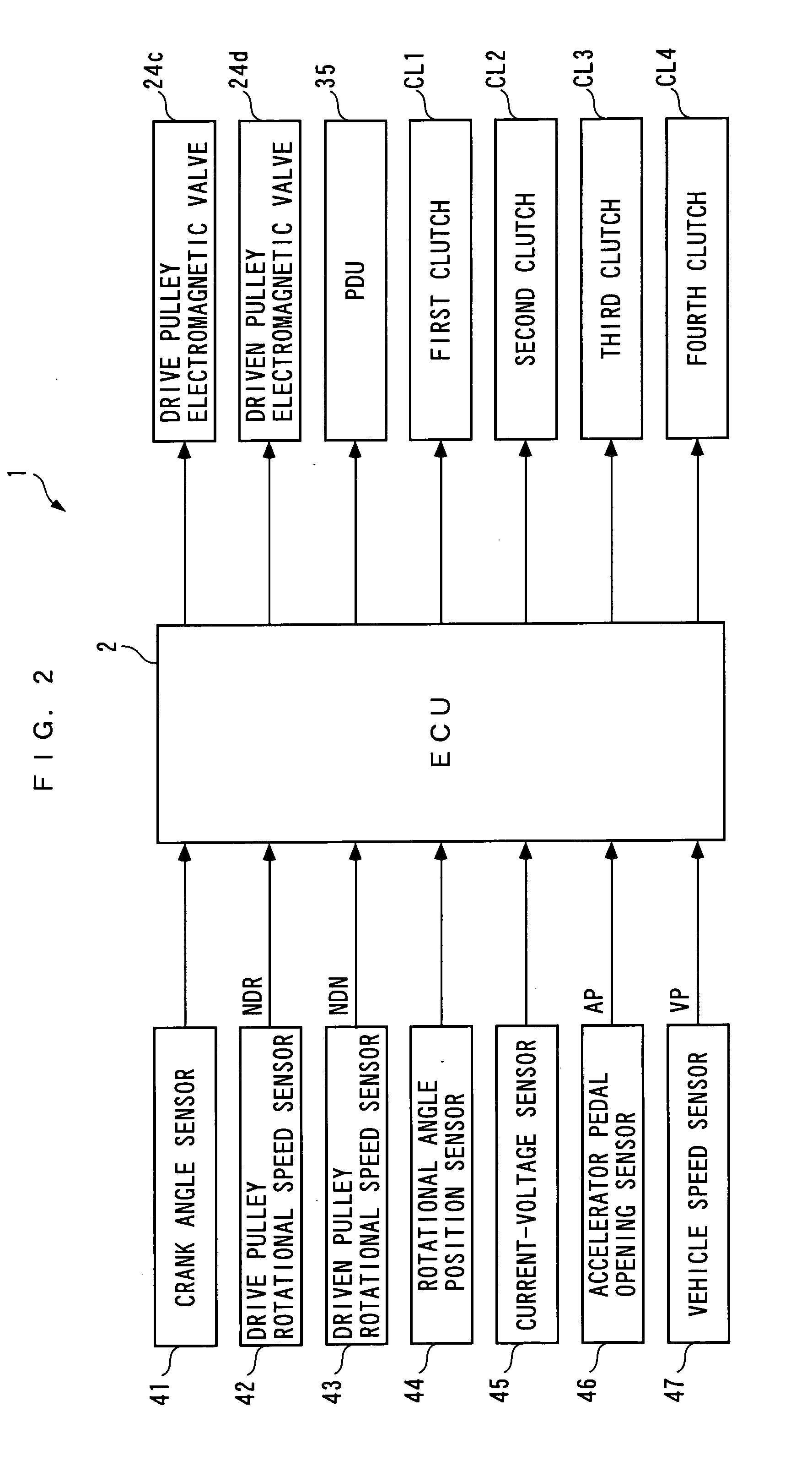
[0026]The present invention will now be described in detail with reference to the drawings showing a preferred embodiment thereof. It should be noted that in the figures, hatching in portions illustrating cross-sections are omitted for convenience. FIG. 1 schematically shows a power plant 1 according to the present embodiment. The power plant 1 is for driving front wheels of the vehicle, i.e. left and right drive wheels DW and DW (driven part) on the front side of a front-driven four-wheel vehicle, not shown, and includes an internal combustion engine 3 (prime mover) and a rotary motor 30 as power sources, and a planetary gear train PS, a stepless transmission 20 (transmission) a differential gear mechanism 12, and right and left drive shafts 13 and 13, for transmitting the driving force to the drive wheels DW and DW. The differential gear mechanism 12 is connected to the drive wheels DW and DW via the drive shafts 13 and 13. Further, as shown in FIG. 2, the power plant 1 is provide...


PUM


Abstract

A power plant which is capable of improving the drive efficiency and the power generation efficiency thereof when the electric power is generated using the power of a driven part thereof. A power plant has an internal combustion engine having a crankshaft, and a rotary motor having a rotor. A planetary gear train includes a sun gear, a ring gear, and a carrier rotatably supporting a planetary gear in mesh with the sun gear and the ring gear. The sun gear and the ring gear are connected to drive wheels. The carrier is connected to the crankshaft. The rotor is connected between one of the sun gear and the ring gear and the drive wheels. A transmission is connected between the other of the gears and the drive wheels, for varying a speed of power of the engine and transmitting the power to the drive wheels.

Description

BACKGROUND OF THE INVENTION[0001]1. Field of the Invention[0002]The present invention relates to a power plant for driving a driven part, and more particularly to a power plant including a prime mover and a rotary motor as power sources.[0003]2. Description of the Related Art[0004]Conventionally, as the power plant of this kind, one disclosed in Japanese Laid-Open Patent Publication (Kokai) No. 2004-175320 is known. This power plant is for driving drive wheels of a vehicle, and is equipped with an internal combustion engine and a motor generator as power sources, and a stepless transmission and a planetary gear train for transmitting power to the drive wheels. The planetary gear train is a general type that has a sun gear, a ring gear, and a carrier, and the sun gear and the ring gear are connected to the drive wheels via a high clutch and a low clutch, respectively. The engine is connected to the carrier via a main shaft, and the main shaft is connected to an input pulley of the st...

Claims


Application Information

Patent Timeline
Patent Type & Authority Patents(United States)
IPC IPC(8): B60K6/00
CPCB60K6/365B60K6/48B60K6/543F16H2037/0866Y02T10/6221Y02T10/62
Inventor ABE, NORIYUKIAKUTSU, SHIGEMITSUOKADA, YOSHIO
Owner HONDA MOTOR CO LTD
Why Eureka
Try Eureka