External oil expansion chamber for seabed boosting ESP equipment

a technology of external oil expansion chamber and seabed boosting, which is applied in the direction of positive displacement liquid engine, piston pump, borehole/well accessories, etc., can solve the problems of reduced motor oil loss and primary chamber contracting, and achieve the effect of effective mechanism, reduced loss of motor oil, and advantageous extension of motor li

Active Publication Date: 2013-07-16
BAKER HUGHES INC
View PDF13 Cites 10 Cited by
  • Summary
  • Abstract
  • Description
  • Claims
  • Application Information

AI Technical Summary

Benefits of technology

[0010]The external expansion chamber arrangement thus provides an effective mechanism for dealing with expanding motor oil without the need of a longer ESP. Leaks due to expanding motor oil decrease and thereby loss of motor oil decreases as does contamination of the motor oil with formation fluid. Thus, the motor life is advantageously extended and its reliability is advantageously increased.

Problems solved by technology

Further, the primary chamber may contract when the motor oil cools down.
Leaks due to expanding motor oil decrease and thereby loss of motor oil decreases as does contamination of the motor oil with formation fluid.

Method used


Image

  • External oil expansion chamber for seabed boosting ESP equipment
  • External oil expansion chamber for seabed boosting ESP equipment
  • External oil expansion chamber for seabed boosting ESP equipment

Examples


Embodiment Construction

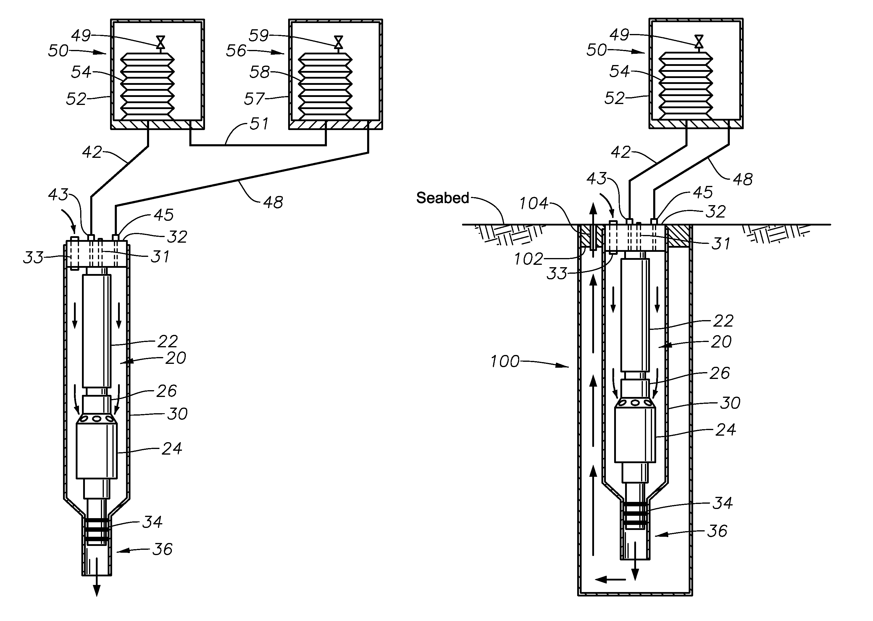
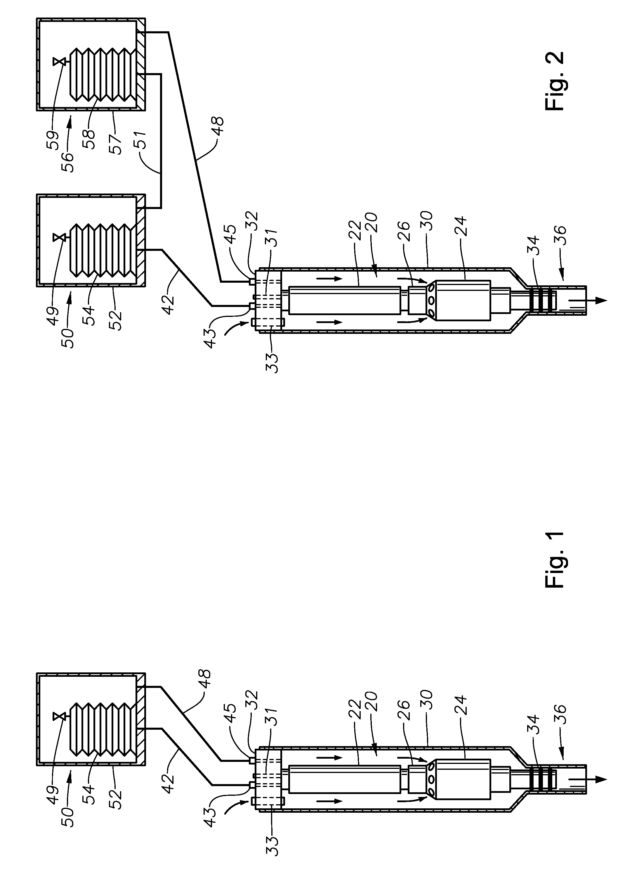
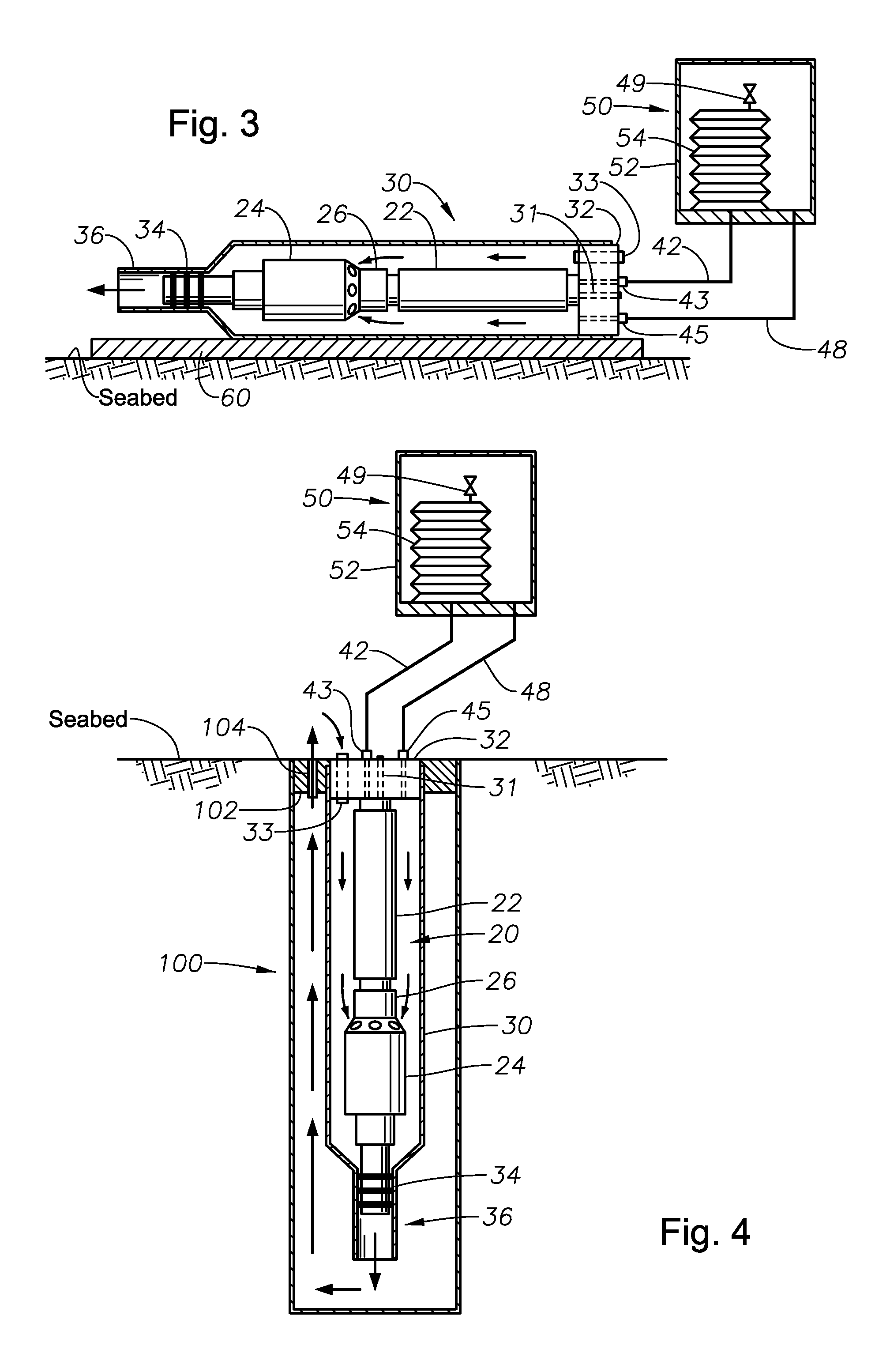
[0021]Referring to FIG. 1, an electrical submersible pump (“ESP”) 20 is illustrated in a sectional view. The ESP 20 can be part of a boosting system located on the seabed. It may be horizontally mounted, inclined, or vertically mounted with a caisson in the seafloor, also referred to as a “dummy well.” A motor 22 and pump 24 are shown with a seal section 26 located in between. The seal section 26 contains a thrust bearing and can contain a pressure equalizer to equalize the pressure of lubricant in the motor 22 with the hydrostatic pressure that allows the motor oil lubricant to thermally expand and contract. The pressure equalizer may be a bellows, a bladder or a labyrinth arrangement. Alternatively, a battery of mechanical seals can be used in the seal section 26.

[0022]A capsule 30 houses the ESP 20 and has a cap or barrier 32 at one end and a discharge port 36 at the other end. Capsule 30 in this example is located on the sea floor and is horizontal or inclined on a skid 60 (FIG....


PUM


Abstract

An expansion chamber to serve ESP equipment installed on the seabed located in either a caisson or a conduit on a skid. The expansion chamber provides an external reservoir for expansion and contraction of motor oil in the ESP equipment. During operation of an ESP, the heat generated in the motor raises the temperature of the motor oil, causing it to expand. The expansion chamber is connected to the ESP equipment via oil lines that allow oil to expand into the expansion chamber when the temperature of the motor oil increases. The expansion chamber has a movable barrier therein that defines primary and secondary chamber. Oil communicates with the primary chamber. Formation fluid within the conduit surrounding the motor communicates with the secondary chamber.

Description

CROSS-REFERENCE TO RELATED APPLICATION[0001]This application claims priority to provisional application 61 / 221,460, filed Jun. 29, 2009.FIELD OF THE INVENTION[0002]This invention relates in general to booster pump electric motors, and in particular to accommodating the expansion and contraction of dielectric lubricant of a sea floor submersible electric pump motor via a subsea expansion chamber.BACKGROUND OF THE INVENTION[0003]Electrical submersible pumps (“ESP”) are used for pumping high volumes of well fluid, particularly in wells requiring artificial lift. The ESP typically has at least one electrical motor that normally is a three-phase, AC motor. The motor drives a centrifugal pump that may contain a plurality of stages, each stage comprising an impeller and a diffuser that increases the pressure of the well fluid. The motor is filled with a dielectric lubricant or oil that provides lubrication and aids in the removal of heat from the motor during operation of the ESP. A seal s...

Claims


Application Information

Patent Timeline
Patent Type & Authority Patents(United States)
IPC IPC(8): F04B35/04H02K5/10H02K5/132
CPCE21B43/128E21B47/011F04D13/08F04D13/10F04D29/086E21B47/017
Inventor MARTINEZ, IGNACIOMERRILL, DAN A.
Owner BAKER HUGHES INC
Why Eureka
Try Eureka