Fluid storage tank configured to remove entrained air from fluid

a technology of fluid storage tank and entrained air, which is applied in the direction of rigid containers, service pipe systems, packaging, etc., can solve the problem of requiring a large amount of fluid storage tank, and achieve the effect of improving the removal of fluid and promoting the nucleation of entrained air

Active Publication Date: 2013-07-23
HELGESEN DESIGN SERVICES
View PDF5 Cites 8 Cited by
  • Summary
  • Abstract
  • Description
  • Claims
  • Application Information

AI Technical Summary

Benefits of technology

[0008]In one embodiment a fluid storage tank having improved air extraction capabilities is provided. The fluid storage tank includes a nucleation plate having nucleation slots formed therein which cause small entrained air bubbles to nucleate or otherwise agglomerate into larger bubbles that have sufficient buoyancy to overcome the flow forces acting on the air bubbles.
[0011]In one embodiment, the nucleation surfaces are preferably angled downward relative to the top surface of the fluid within the fluid storage tank when traveling in the downstream direction. This directs the fluid flow away from the surface of the tank to inhibit turbulence production at the fluid surface of the tank to inhibit further air entrainment. Further, the nucleation plate including these nucleation slots is preferably angled relative to the top surface of the fluid. This angle is preferably between about 30 and 60 degrees and more preferably between about 40 and 50 degrees. This angle also causes the fluid bubbles formed on the top surface of the nucleation slots to be pressed into the top surface rather than pressed off of the surfaces such that it is more difficult to discharge the consolidating bubbles from the nucleation surfaces allowing increased bubble size formation. However, other embodiments may have a surface roughness of less than 135 Ra.
[0012]In other embodiments, the nucleation surfaces may be angled upward relative to the top surface of fluid. This arrangement reduces fluid flow resistance (i.e. back pressure) allowing the fluid to flow through the slots at a slower rate. These arrangements typically have an angle of between about 120 to 150 degrees and more preferably 130 to 140 degrees and preferably about 135 degrees.
[0016]In a further embodiment, the fluid storage tank includes at least an inlet zone and an air-extraction zone. The inlet zone is immediately upstream of the nucleation slots and the air-extraction zone is immediately downstream of the nucleation slots. The top of the inlet zone is vertically lower than the top of the air-extraction zone. Further, in operation, the hydraulic fluid level is maintained at a depth that is higher than the top of the inlet zone at all times. This prevents an air-hydraulic fluid interface within the inlet zone reducing the amount of air entrainment due to turbulence generated by the hydraulic fluid as it enters the inlet zone.

Problems solved by technology

Unfortunately, return hydraulic fluid from a hydraulic system contains entrained air in the form of microscopic bubbles.
Unfortunately, larger tank sizes are typically required to extract this excess heat.

Method used


Image

  • Fluid storage tank configured to remove entrained air from fluid
  • Fluid storage tank configured to remove entrained air from fluid
  • Fluid storage tank configured to remove entrained air from fluid

Examples


Embodiment Construction

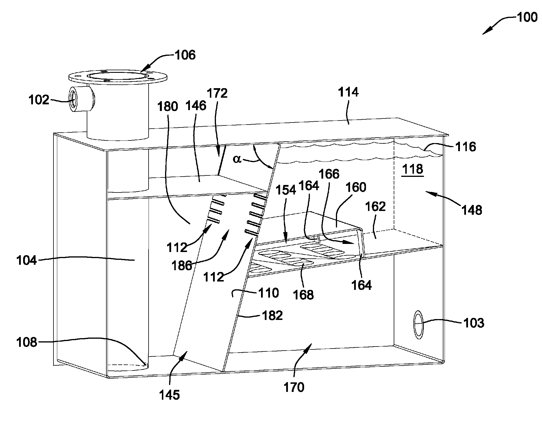
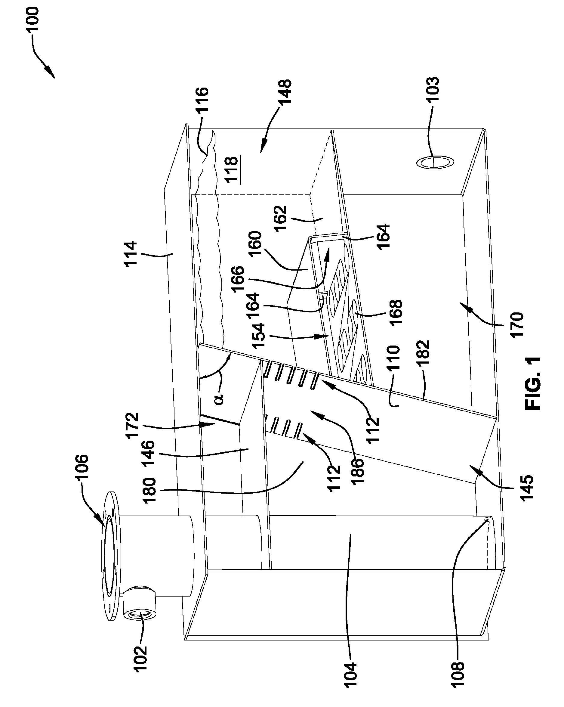
[0028]FIG. 1 is a perspective illustration of a fluid storage tank 100 according to an embodiment of the present invention. The fluid storage tank 100 is used to store fluid for use in a down stream system (not shown). In one embodiment, the system is a hydraulic system that uses the fluid as a means for transmitting power to or from devices of the system, such as hydraulic motors, pumps, cylinders, etc.

[0029]The fluid storage tank 100 includes a fluid inlet 102 where return fluid that has passed through the system returns to the fluid storage tank 100. The inlet 102 may be in the form of a threaded coupling, a quick connect coupling, or other coupling to which a fluid conduit or hose may be connected. The fluid storage tank 100 also includes an outlet 103 through which the stored fluid exits the fluid storage tank 100. This outlet 103 can be similar to the inlet 102. Typically, the outlet 103 is coupled to a source of suction such as a hydraulic pump.

[0030]In this particular embodi...


PUM

PropertyMeasurementUnit
thicknessaaaaaaaaaa
thicknessaaaaaaaaaa
angleaaaaaaaaaa

Abstract

A fluid storage tank including an entrained air removal mechanism is provided. The entrained air removal mechanism assists in consolidating small air bubbles entrained within the fluid into larger bubbles such that the air bubbles have sufficient buoyancy to escape the fluid flow. The entrained air removal mechanism may be in the form of a plurality of saw toothed slots communicating different chambers within the fluid storage tank. The fluid storage tank can also be configured to direct fluid flow towards the sidewalls of the fluid storage tank as the fluid transitions from one chamber to another to promote heat transfer out of the fluid storage tank and to avoid the fluid within the tank acting as a thermal insulator.

Description

CROSS-REFERENCE TO RELATED PATENT APPLICATIONS[0001]This patent application claims the benefit of U.S. Provisional Patent Application No. 61 / 347,678, filed May 24, 2010, the entire teachings and disclosure of which are incorporated herein by reference thereto.FIELD OF THE INVENTION[0002]This invention generally relates to fluid storage tanks and more particularly to fluid storage tanks that remove entrained air and heat from the fluid stored therein.BACKGROUND OF THE INVENTION[0003]Many devices use fluid as a means to power other devices. For instance, many devices such as trucks, heavy equipment, construction equipment, farm equipment, etc. will utilize a hydraulic system that uses pressurized hydraulic fluid (typically oil) to run hydraulic motors, drive hydraulic cylinders, etc.[0004]Unfortunately, return hydraulic fluid from a hydraulic system contains entrained air in the form of microscopic bubbles. The source of this air can be a number of locations such as hydraulic cylinder...

Claims


Application Information

Patent Timeline
Patent Type & Authority Patents(United States)
IPC IPC(8): B01D45/00F15B21/044
CPCF15B1/26F15B21/044Y10T137/0318Y10T137/86212Y10T137/794
Inventor KNUTH, BRUCE E.
Owner HELGESEN DESIGN SERVICES
Why Eureka
Try Eureka