Method and apparatus to provide a clock signal to a charge pump

a charge pump and clock signal technology, applied in the direction of generating/distributing signals, process and machine control, etc., can solve the problems of relatively low output ripple voltage, and large output ripple voltage of the charge pump

Inactive Publication Date: 2013-07-23
QUALCOMM INC
View PDF12 Cites 15 Cited by
  • Summary
  • Abstract
  • Description
  • Claims
  • Application Information

AI Technical Summary

Benefits of technology

[0005]The voltage boost method and circuit also reduces the size of the capacitors utilized by the charge pump units as a result of a falling and a rising edge occurring substantially concurrently on every transition other than the first transition when the clock is enabled and the final transition when the clock is disabled. Since a big portion of total charge pump is capacitor area this reduction in capacitor size will lead to total area reduction in silicon. In addition to the reduced area advantage, a smaller capacitance further reduces the output ripple voltage when the clock is disabled.
[0009]One particular advantage provided by at least one of the disclosed embodiments is that the ripple voltage on the output of the charge pump is reduced. Thus, an enhanced method and circuit for a charge pump having a low output ripple voltage is provided.

Problems solved by technology

However, when the multiphase clock is disabled, the charge pump may produce a relatively large output ripple voltage that exceeds a determined tolerance.
A single falling edge transition when the clock is disabled results in a relatively low output ripple voltage.

Method used


Image

  • Method and apparatus to provide a clock signal to a charge pump
  • Method and apparatus to provide a clock signal to a charge pump
  • Method and apparatus to provide a clock signal to a charge pump

Examples


Embodiment Construction

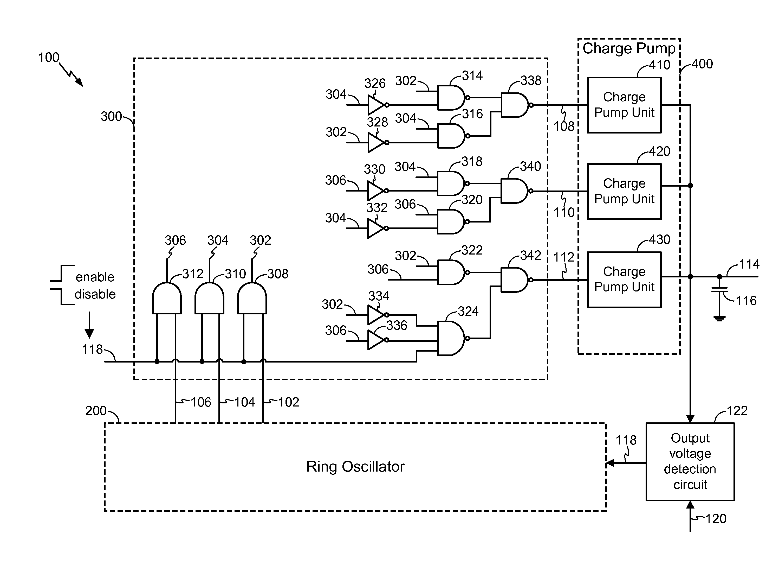
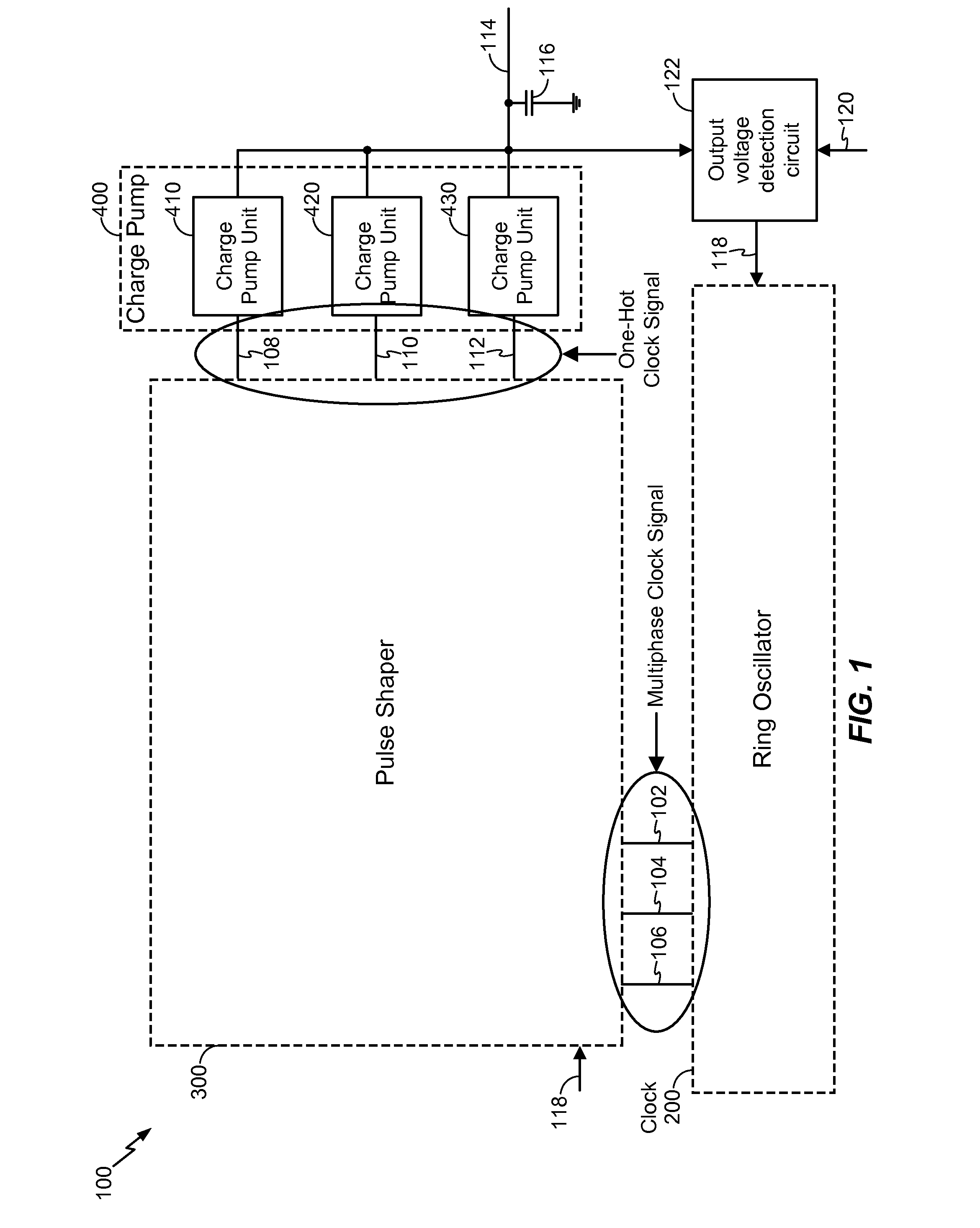
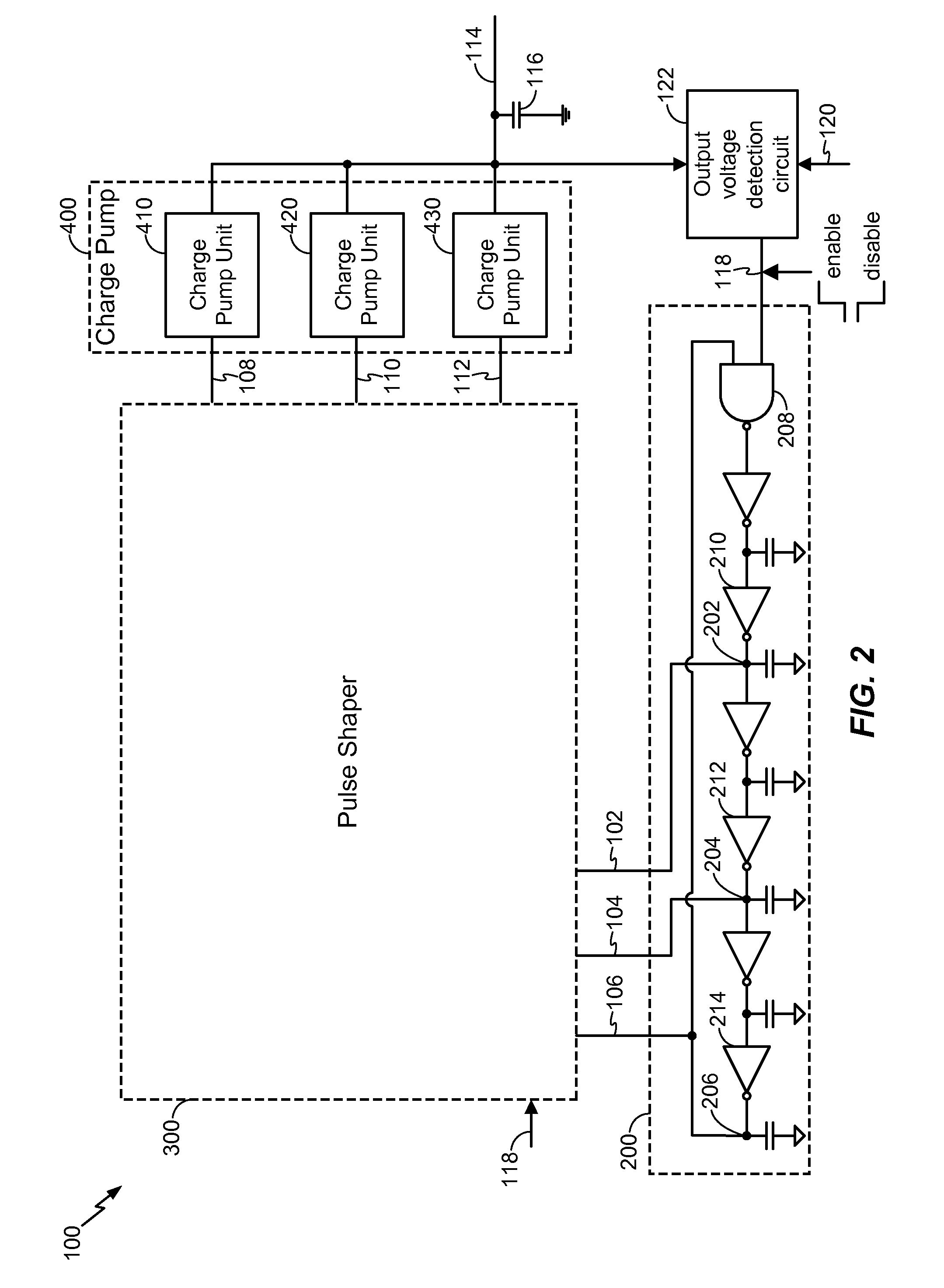
[0024]Referring to FIG. 1, a particular illustrative embodiment of a circuit that includes a voltage boost circuit 100 is illustrated. The voltage boost circuit 100 includes a ring oscillator 200, a pulse shaper 300, a charge pump 400, and an output voltage detection circuit 122. The charge pump 400 includes multiple charge pump units. For example, the charge pump 400 includes a first charge pump unit 410, a second charge pump unit 420, and a third charge pump unit 430. While three charge pump units are shown with respect to FIG. 1, it should be understood that the charge pump 400 may include more or fewer charge pump units than shown.

[0025]In a particular illustrative embodiment, the output voltage detection circuit 122 receives a voltage output 114 of the charge pump 400 and receives a reference voltage 120. Based on the voltage output 114 and the reference voltage 120, the output voltage detection circuit 122 provides a control signal 118 to enable or disable the ring oscillator ...


PUM


Abstract

A method and apparatus for providing a clock signal to a charge pump is disclosed. In a particular embodiment, the method includes providing a first clock signal to a first charge pump unit of a charge pump. The method further includes providing a second clock signal to a second charge pump unit of the charge pump. A low-to-high transition of the first clock signal occurs substantially concurrently with a high-to-low transition of the second clock signal. Only one clock signal may be at a logic high voltage level at any given time.

Description

I. FIELD[0001]The present disclosure is generally related to a method and an apparatus for providing a clock signal to a charge pump.II. DESCRIPTION OF RELATED ART[0002]Advances in technology have resulted in smaller and more powerful computing devices. For example, there currently exist a variety of portable personal computing devices, including wireless computing devices, such as portable wireless telephones, personal digital assistants (PDAs), and paging devices that are small, lightweight, and easily carried by users. More specifically, portable wireless telephones, such as cellular telephones and internet protocol (IP) telephones, can communicate voice and data packets over wireless networks. Further, many such wireless telephones include other types of devices that are incorporated therein. For example, a wireless telephone can also include a digital still camera, a digital video camera, a digital recorder, and an audio file player. Also, such wireless telephones can process e...

Claims


Application Information

Patent Timeline
Patent Type & Authority Patents(United States)
IPC IPC(8): G05F1/10
CPCG06F1/06H02M3/073H02M3/07H02M2003/077H02M3/077G06F1/26G06F1/10G05F3/02
Inventor HAO, WUYANGKIM, JUNG PILLSUH, JUNGWON
Owner QUALCOMM INC
Why Eureka
Try Eureka