In all cases, the turnaround procedure is critical since the expense involved in keeping the
plant inactive can amount to several millions of dollars per day.
These periods are usually spring and autumn, since summer is unsuitably hot for anything other than emergency work and for refineries, winter is usually the peak production season.
Because of the nature of the environment, the work is potentially very dangerous.
This factor, combined with the limited mental ability of certain workers and the
time pressure under which the operation takes place result in the need for exceptional attention to all aspects of safety.
Most of the time however, the safety officers only intermittently observe.
Such inactivity leads to boredom and frequently they may become distracted, lose concentration and even fall asleep or go off for a coffee.
A major problem with work in such environments is the lack of continuous attention to safety and a tendency by both workers and “safety” officers to
cut-corners wherever possible or shirk responsibility.
Even when the safety officers act conscientiously, since much of the work takes place out of
sight within the confined space, rigorous observation of the work is difficult or incomplete.
It can also occur that the contents of the
plant e.g. a catalytic column are unstable in air.
Clearly, it is impossible for the safety officer to effectively monitor without entering the sealed environment and being exposed to the danger himself.
Periodic measurement of the air composition at the access opening does not always provide a reliable indication of the actual condition under which the personnel are working.
In addition to possible risks of explosion, many of the gases encountered are potentially dangerous, especially in large doses.
Such inspections are however difficult to achieve when the work proceeds at a
high rate.
Once a layer has been completed it is no longer possible to determine whether the layer below has been correctly assembled.
At present, no
system is available which meets these stringent requirements.
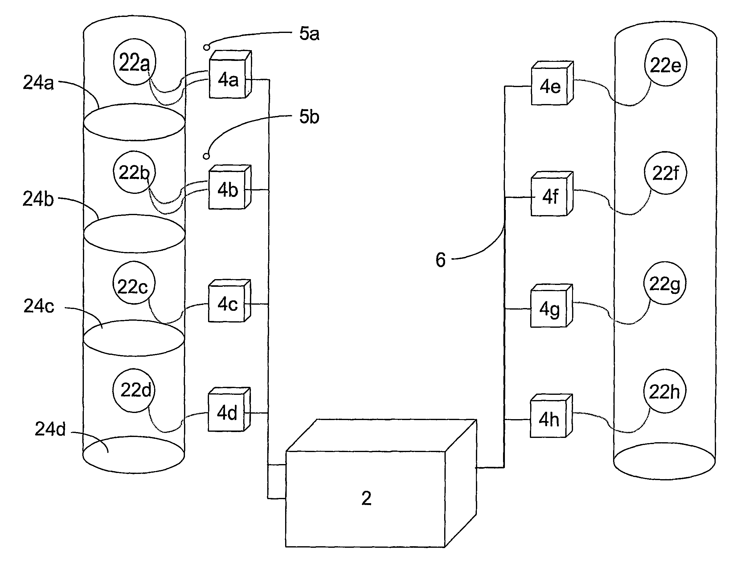
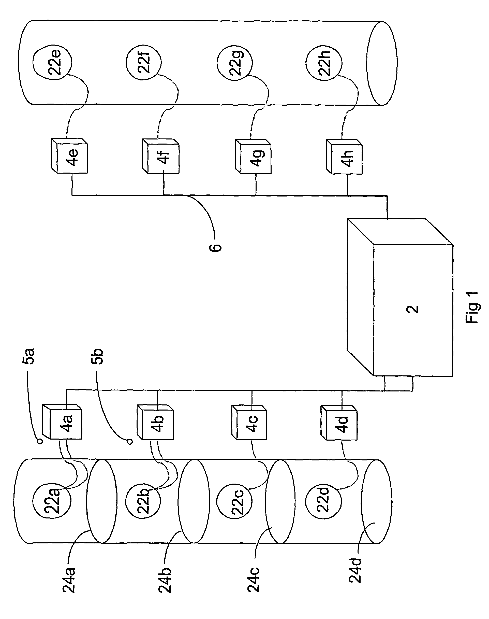
Such systems are however designed to be permanently integrated into a
building environment and are not adapted for mobile deployment at a workplace.
In particular, the use of
radio transmission between the
video camera and monitor is unsuitable for use in the context of
refinery fractionating columns where transmission is impeded by the steel wall of the column.
Furthermore, they are generally of a construction and configuration which makes them unsuitable for use in a workplace.
This
system is neither contemplated nor adapted for ensuring the safety of the operating personnel.

