Method of and apparatus for power factor correction in a power supply

a power factor and power supply technology, applied in the direction of electric variable regulation, process and machine control, instruments, etc., can solve the problems of reducing efficiency, reliability, and weight of the approach, and reducing the efficiency of the design

Active Publication Date: 2013-07-23
ROCKWELL COLLINS INC
View PDF6 Cites 38 Cited by
  • Summary
  • Abstract
  • Description
  • Claims
  • Application Information

AI Technical Summary

Benefits of technology

This patent describes a converter that can balance the current supplied by three power stages. It includes an active control circuit that receives feedback signals from the power stages and adjusts the control signals accordingly. This allows for a more efficient and balanced use of power. The technical effect of this invention is a more reliable and efficient power conversion for aircraft and other systems.

Problems solved by technology

This approach is a heavy and bulky generally not desirable for aircraft applications.
In addition, components associated with such a design can be expensive.
The topology for this circuit has several drawbacks including reduced efficiency, reliability, high in-rush current, and high parts count.
Usage of the Single-Ended Primary Inductance Converters (SEPIC) operating in continuous conduction mode have not been widely utilized in power factor correction applications due to poor performance caused by power stage circuit resonance.
The degraded performance is due to the need to limit bandwidth to avoid control loop instability caused by resonance between the coupling capacitor and circuit inductance.
Active clamps can also increase efficiency using a soft switching technique, however the active clamp can add significant complexity and can be difficult to implement reliably due to high voltages in the primary circuit.
Previous attempts to implement individual converters operating from each phase combined into one single output often interact in an undesirable manner.

Method used


Image

  • Method of and apparatus for power factor correction in a power supply
  • Method of and apparatus for power factor correction in a power supply
  • Method of and apparatus for power factor correction in a power supply

Examples


Embodiment Construction

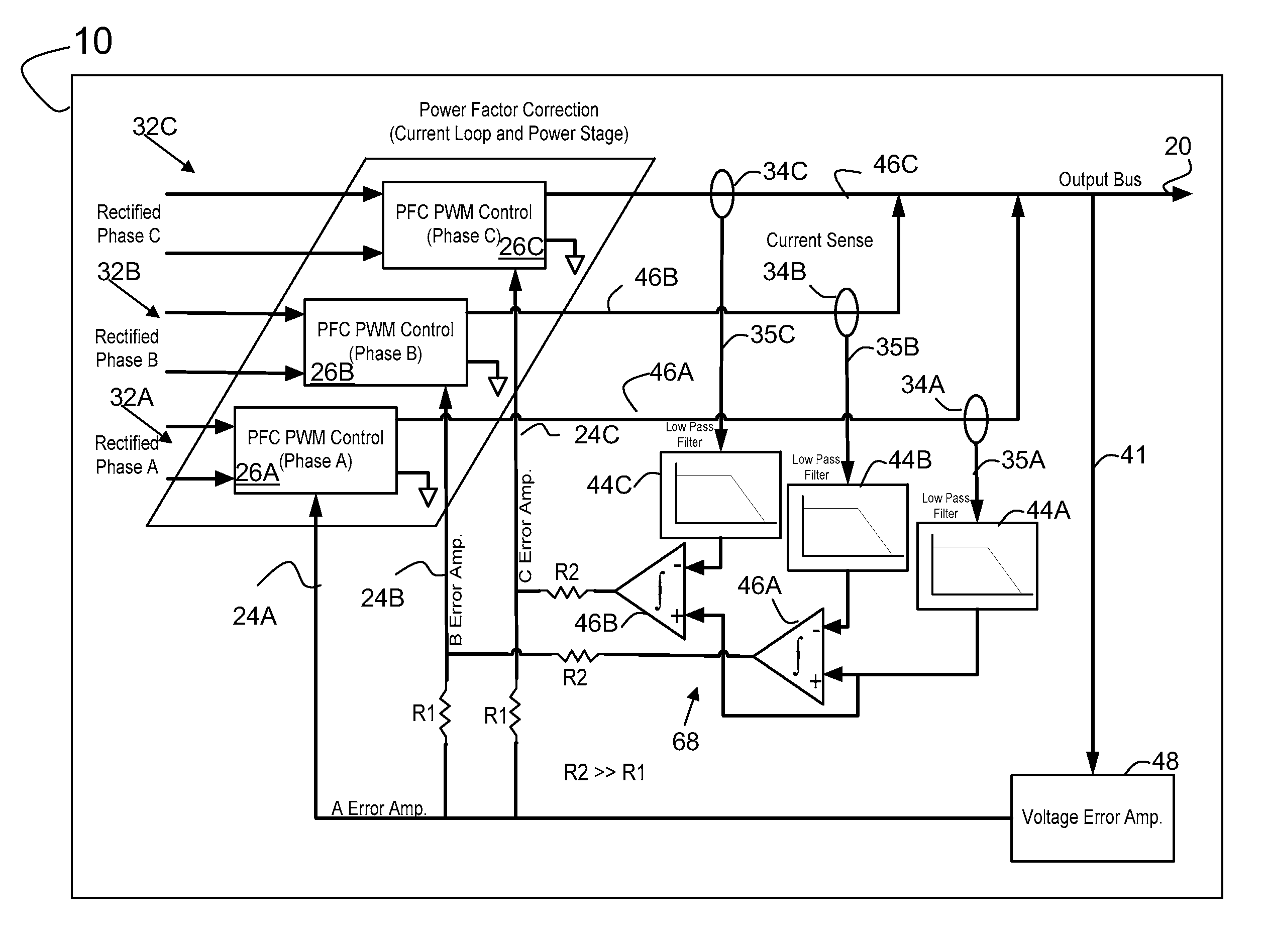
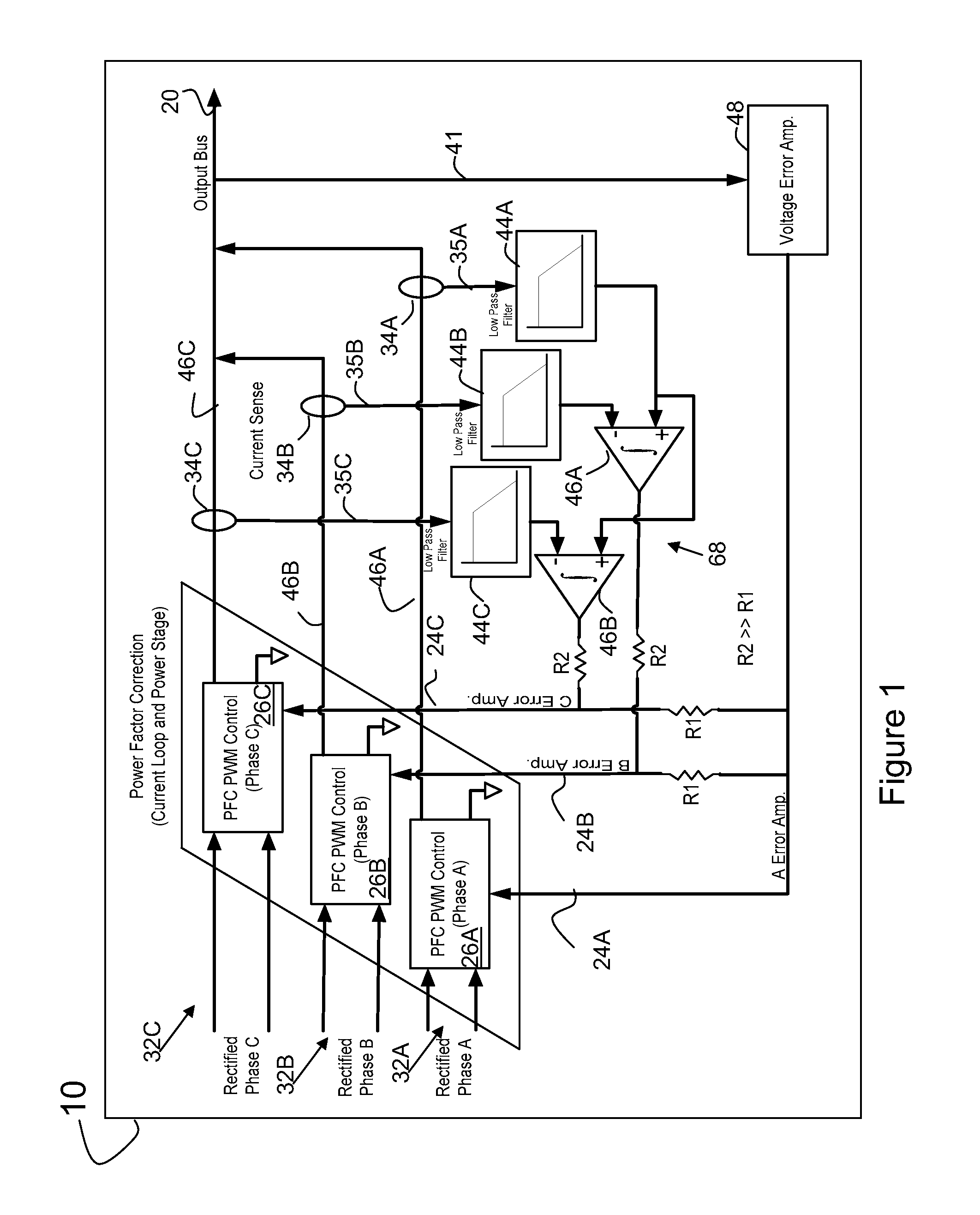
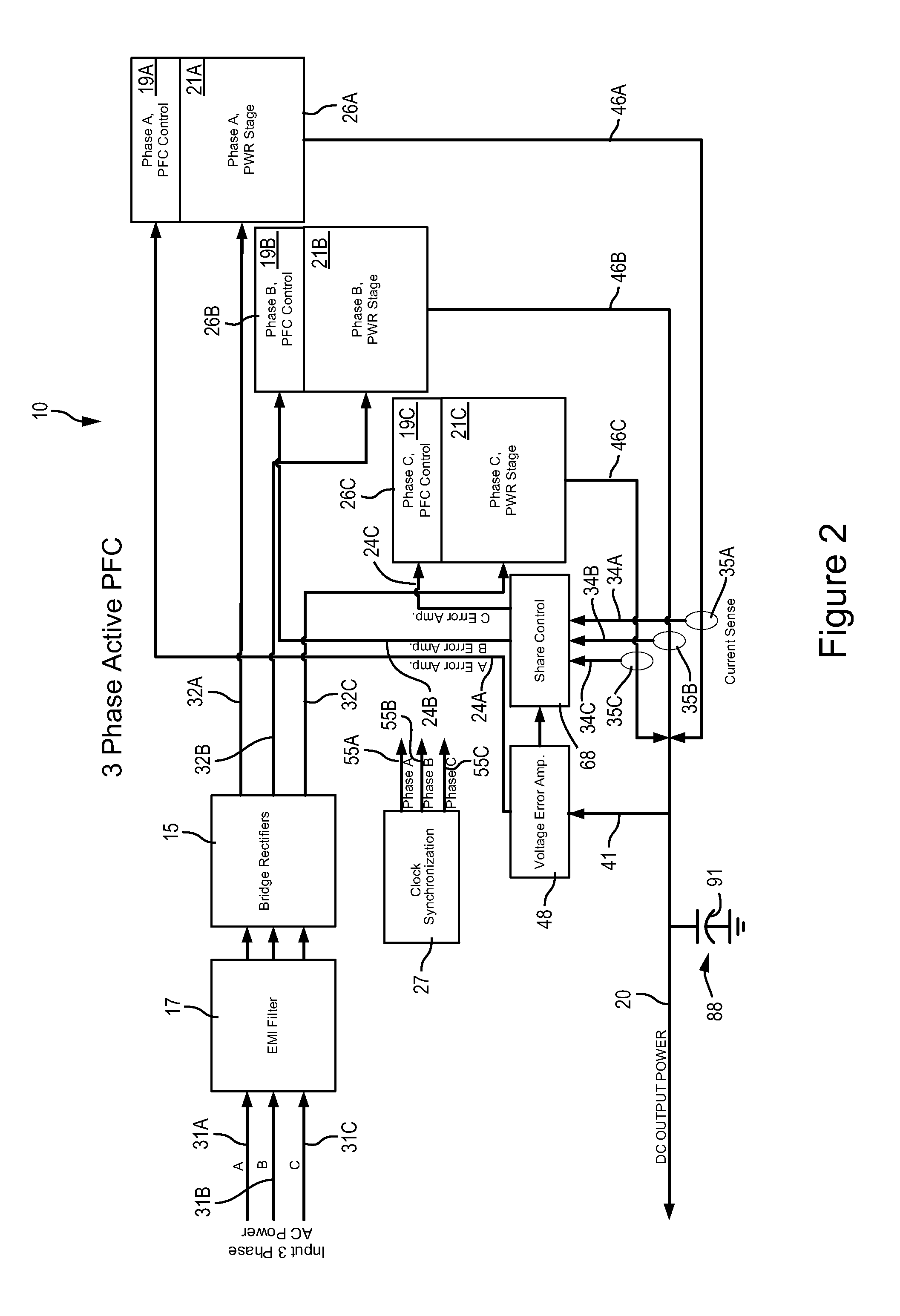
[0024]Before describing in detail the particular improved system and method, it should be observed that the invention includes, but is not limited to, a novel structural combination of conventional components and not to the particular detailed configurations thereof. Accordingly, the structure, methods, functions, control, and arrangement of conventional components, circuits and signals have, for the most part, been illustrated in drawings, by readily understandable block representations and schematic guidelines, in order not to obscure the disclosure with structural details which will be readily apparent to those skilled in the art having the benefit of the description herein. Further, the invention is not limited to the particular embodiments detected in the exemplary diagrams or described herein, but should be construed in accordance with the language in the claims.

[0025]According to one preferred embodiment, a power supply can be a three phase input high power factor Single Ende...


PUM


Abstract

A converter can include at least two power stages. Each power stage can include a power factor control circuit. An active shared control circuit for a three power stage system receives at least three sense signals. Each of the sense signals is associated with a parameter of the respective one of the power stages. The control circuit provides at least three control signals. Each of the control signals being associated with the respective power factor control circuit of the power stages. The active share control circuit balances the current supplied by the power stages via the control signals.

Description

BACKGROUND OF THE INVENTION[0001]The present application generally relates to power circuits. More particularly, the present application relates to a power converter.[0002]Power converters are utilized on a multitude of applications where power conversion is required, such as, in power supply applications. One such application includes supplying power to electronic equipment on-board an aircraft. Aircraft power supplies can be used to supply power to a variety of equipment, including but not limited to radios, computers, navigation equipment, flight controls, radar, sensors, etc.[0003]Conventional aircraft power supplies operating at high power levels generally receive three phase alternating current (AC) input power and use line frequency transformers. This approach is a heavy and bulky generally not desirable for aircraft applications.[0004]Generally, conventional aircraft three phase power supplies have relied on passive techniques to meet power factor and harmonic current requir...

Claims


Application Information

Patent Timeline
IPC IPC(8): H02J1/10
CPCH02M1/4216H02M1/4258Y02B70/126Y02B70/10
Inventor WAMBSGANSS, WARREN J.PETERSON, BRENT C.
Owner ROCKWELL COLLINS INC
Why Eureka
Try Eureka