Image forming apparatus controlling power from a commercial AC power supply to a heater and detecting current flowing in a power supply path from the commercial AC power supply to the heater
a technology of image forming apparatus and power supply path, which is applied in the direction of electrographic process apparatus, instruments, optics, etc., can solve the problems of harmonic current and switching noise generation, and flicker more likely to occur, so as to improve the accuracy of current detection
- Summary
- Abstract
- Description
- Claims
- Application Information
AI Technical Summary
Benefits of technology
Problems solved by technology
Method used
Image

Examples
first embodiment
[0047](Structure of Image Forming Apparatus)
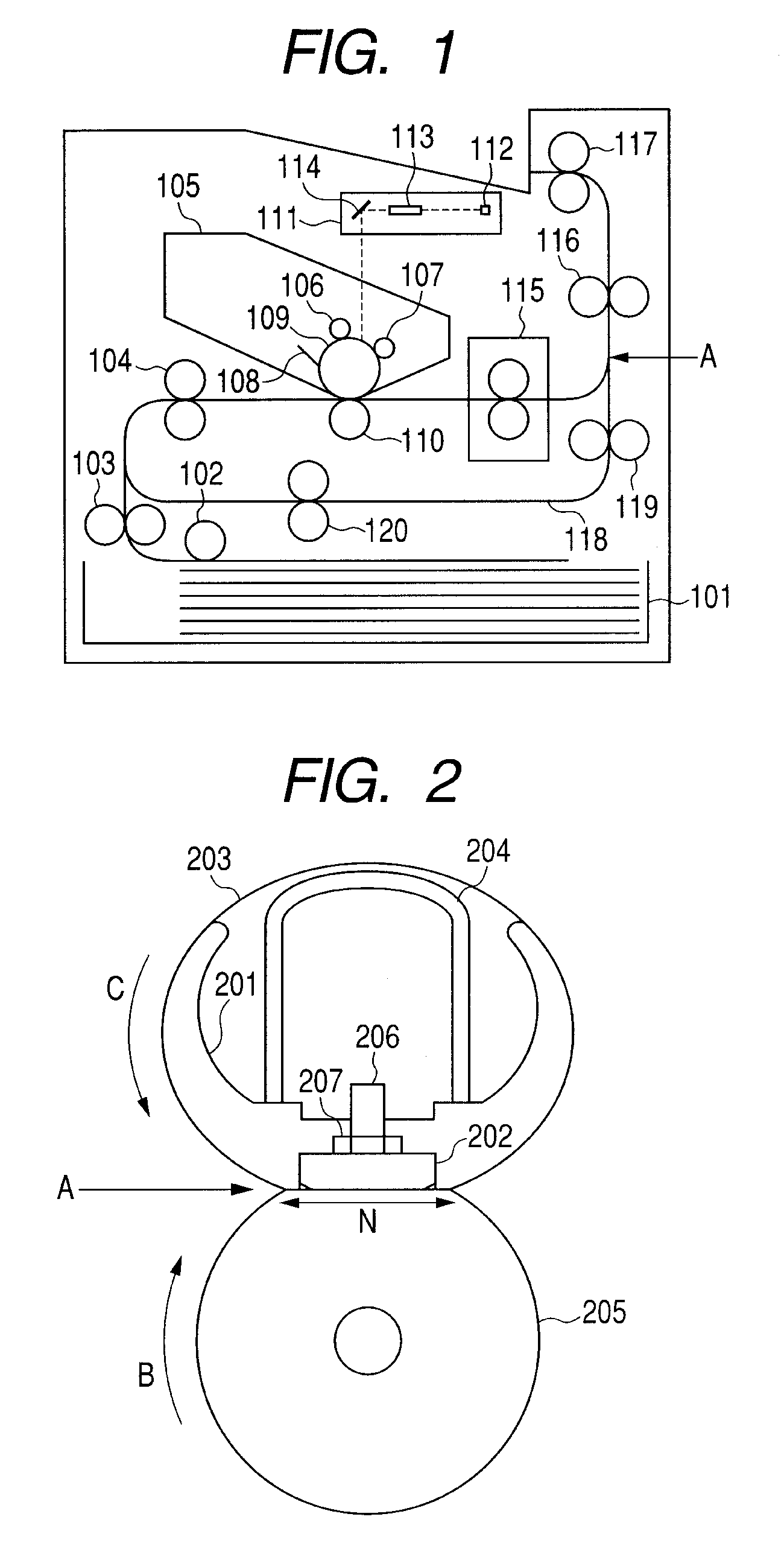
[0048]FIG. 1 illustrates a structure of an image forming apparatus according to a first embodiment of the present invention. Only one of the recording materials stacked in a sheet feeding cassette 101 is sent from the sheet feeding cassette 101 by a pickup roller 102, and is conveyed toward registration rollers 104 by sheet feeding rollers 103. Further, the recording material is conveyed to a process cartridge 105 by the registration rollers 104 at a predetermined timing. The process cartridge 105 integrally includes a charger 106 serving as a charging unit, a developing roller 107 serving as a developing unit, a cleaner 108 serving as a cleaning unit, and a photosensitive drum 109 serving as an electronic photosensitive member. In the image forming apparatus having such a structure, an unfixed toner image is formed on the recording material by a series of process of a known electrophotographic process.
[0049]After the photosensitive drum 1...
second embodiment
[0128]In a second embodiment of the present invention, description of the structure, the configuration, and the control that are common with the first embodiment is omitted. The second embodiment is described by using the same reference symbols for the same components as those of the first embodiment.
[0129](Control of Power Supplied to Ceramic Heater)
[0130]FIG. 15 illustrates the driving circuit, the control circuit, and a power supply circuit for supplying power to the image forming apparatus, of the heater 202 according to this embodiment. In this embodiment, a current detection transformer 1712 is located in such a position as to detect a current that combines a heater current Ih flowing in the heater 202 and a PFC current Ipfc flowing in a power factor circuit (hereinafter, referred to merely as “PFC”) 1701 of a low-voltage power supply (power supply circuit). That is, the image forming apparatus includes the power supply circuit connected to a line branched halfway through a po...
third embodiment
[0151]In a third embodiment of the present invention, description of the structure, the configuration, and the control that are common with the first embodiment is omitted. The third embodiment is described by using the same reference symbols for the same components as those of the first embodiment.
[0152](Control of Power Supplied to Ceramic Heater)
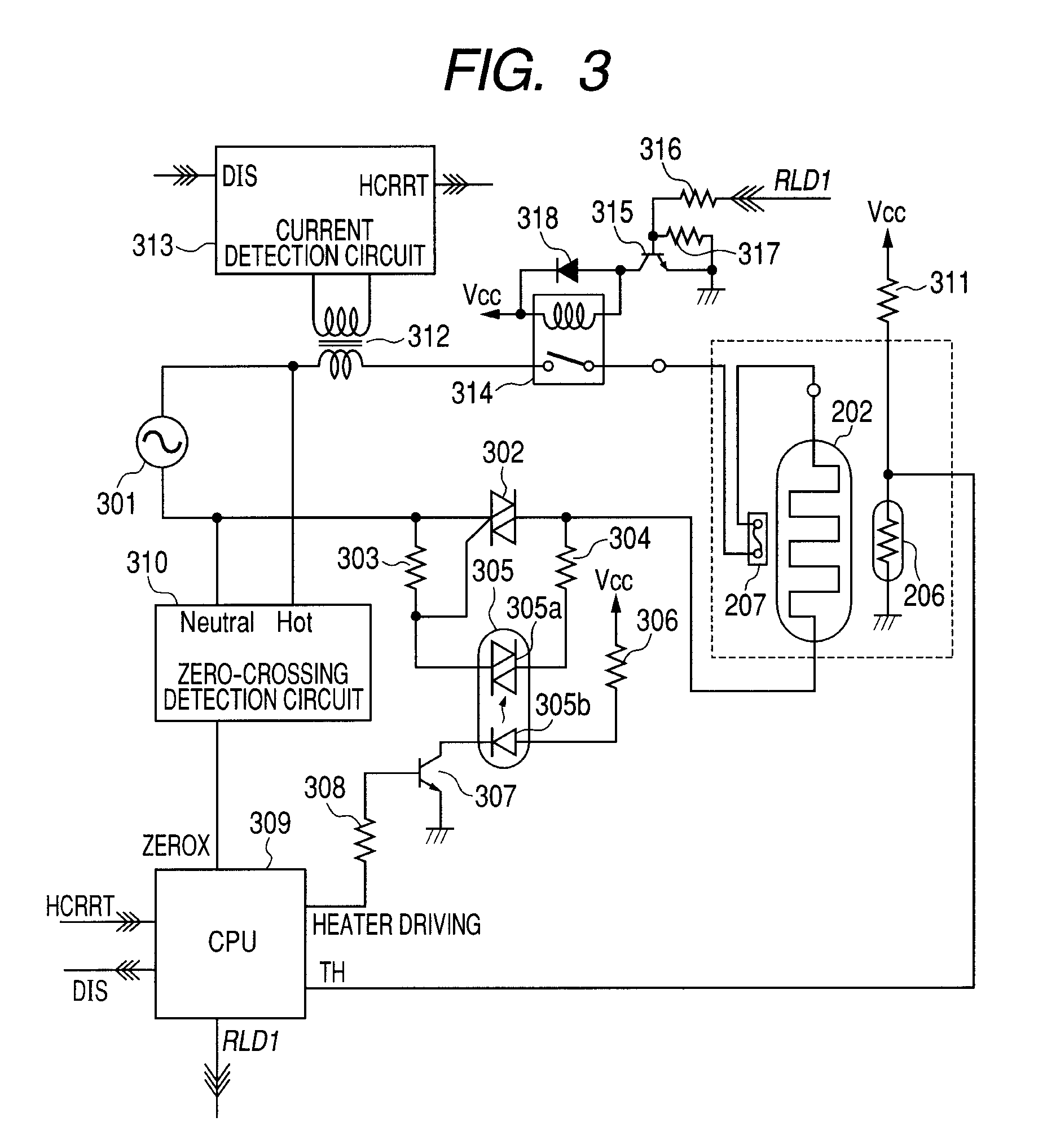
[0153]FIG. 19 illustrates the driving circuit and the control circuit of the heater 202 according to the third embodiment. The current detection transformer 312 voltage-transforms a current on the primary side caused to flow to the heater 202, and performs an input to the current detection circuit 313 on the secondary side. The current detection circuit 313 performs the same operation as in the first embodiment as described with reference to FIGS. 5 and 6, and hence the description thereof is omitted. The secondary-side output from the current detection transformer 312 is input to a current detection circuit 2313 via a phase reverse circu...
PUM
 Abstract
Description
Claims
Application Information