
Guard lock for a component for closing an opening

a technology for components and guard locks, applied in the direction of coatings, structural/machine measurement, instruments, etc., can solve the problems of not being used in safety-related guard locks, and achieve the effects of high transmission/“lever action”, simple plan, and simple structur

Active Publication Date: 2013-07-23
K A SCHMERSAL HLDG
View PDF12 Cites 21 Cited by
  • Summary
  • Abstract
  • Description
  • Claims
  • Application Information

AI Technical Summary

Benefits of technology

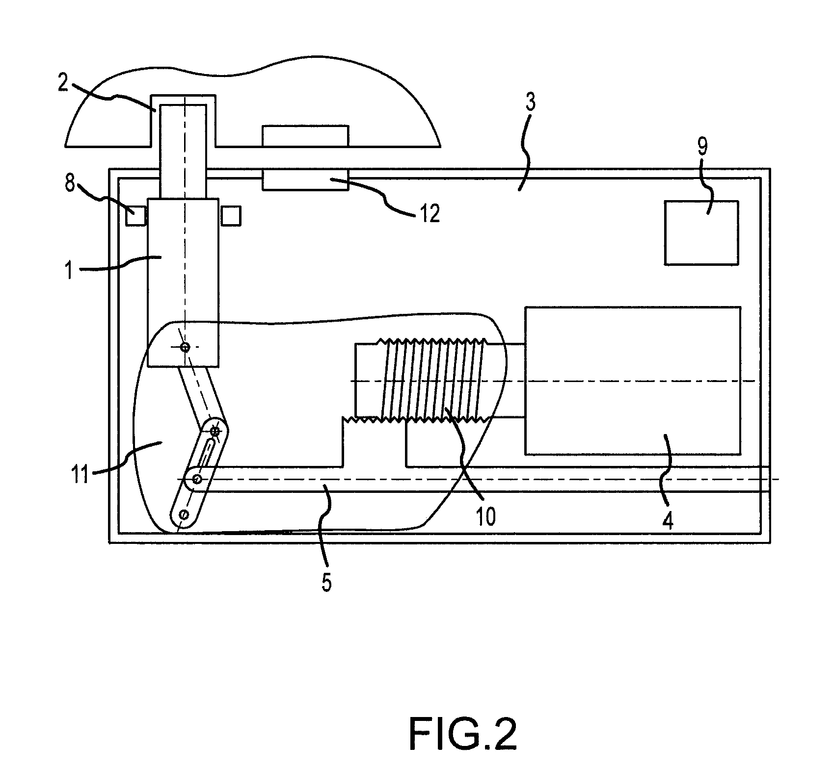
The invention is a safety-related lock that uses an electromagnet arrangement to achieve a fast response and high safety standards. The speed of the lock is not critical, as it can still meet safety requirements even with a relatively low bolt speed compared to an "instantaneous" actuation via an electromagnet. The bolt can implement a travel of 20 mm in one or two seconds, which is sufficient for safety requirements and machine operator's handling. The electric motor has a limited current consumption of 800 mA, with a high movement power of the bolt. A further sensor is provided to determine the reaching of the end positions of the bolt. The transmission device is simple and cost-effective, using a spur gear and a toothed rack or a worm gear and a toggle lever assembly. The sensor can be a light barrier, RFID sensor, pulse-echo sensor, mechanical contact, or Hall sensor, depending on external conditions and manipulation safety.

Problems solved by technology

Although alternative drives for the electromagnet arrangement have already long been known in other fields, they have not been used in safety-related guard locks owing to the prejudice held by those in the technical field since an electromagnet arrangement responds quickly, has a robust design and is relatively inexpensive in terms of manufacture.
Using a component other than an electromagnet for actuating the bolt has been repeatedly ruled out owing to these considerations since there has also been the concern that there would be an interferenced in terms of the electromagnetic fields occurring in the case of an electric motor, which would absolutely rule out the use thereof for a safety-related component.

Method used


Image

  • Guard lock for a component for closing an opening
  • Guard lock for a component for closing an opening
  • Guard lock for a component for closing an opening

Examples


Embodiment Construction

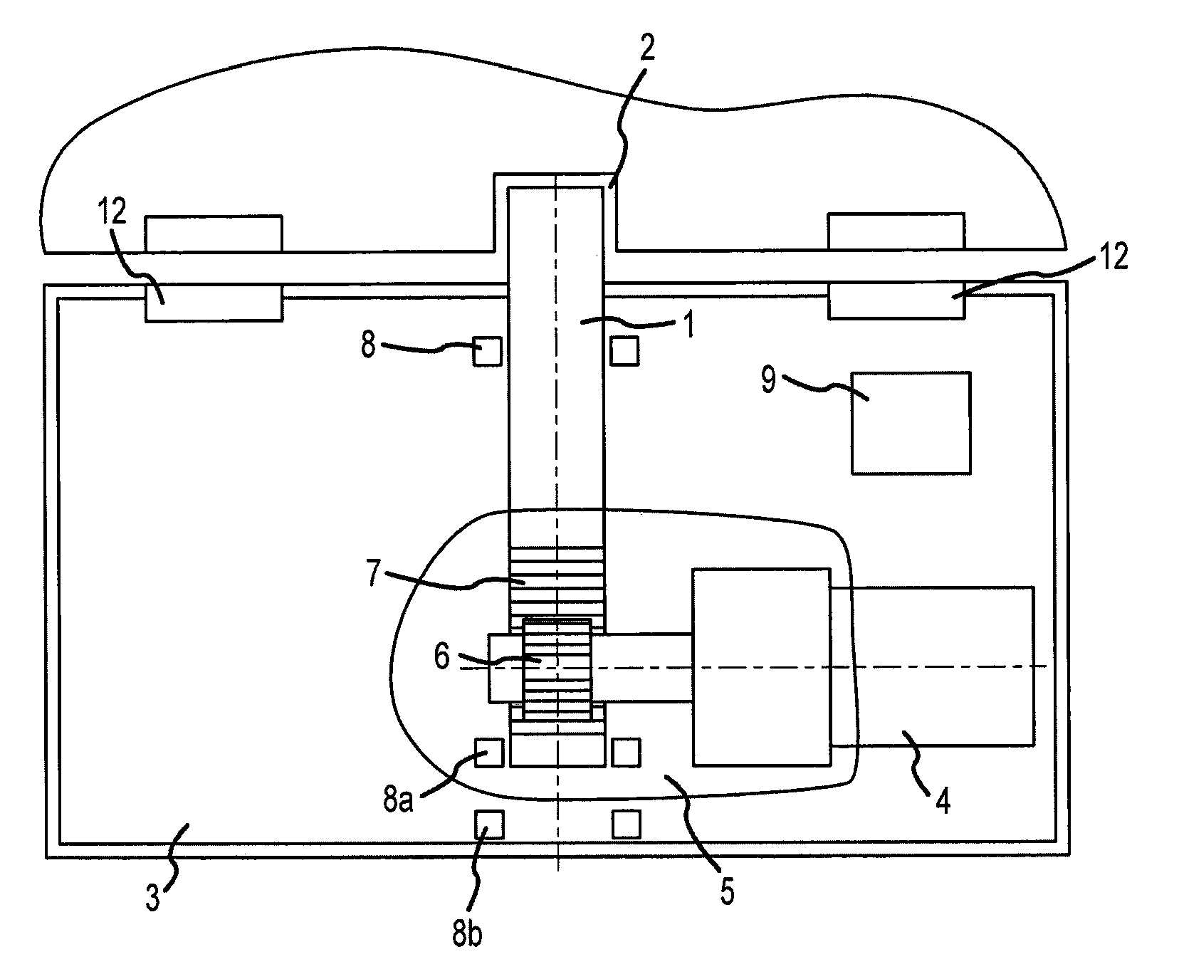
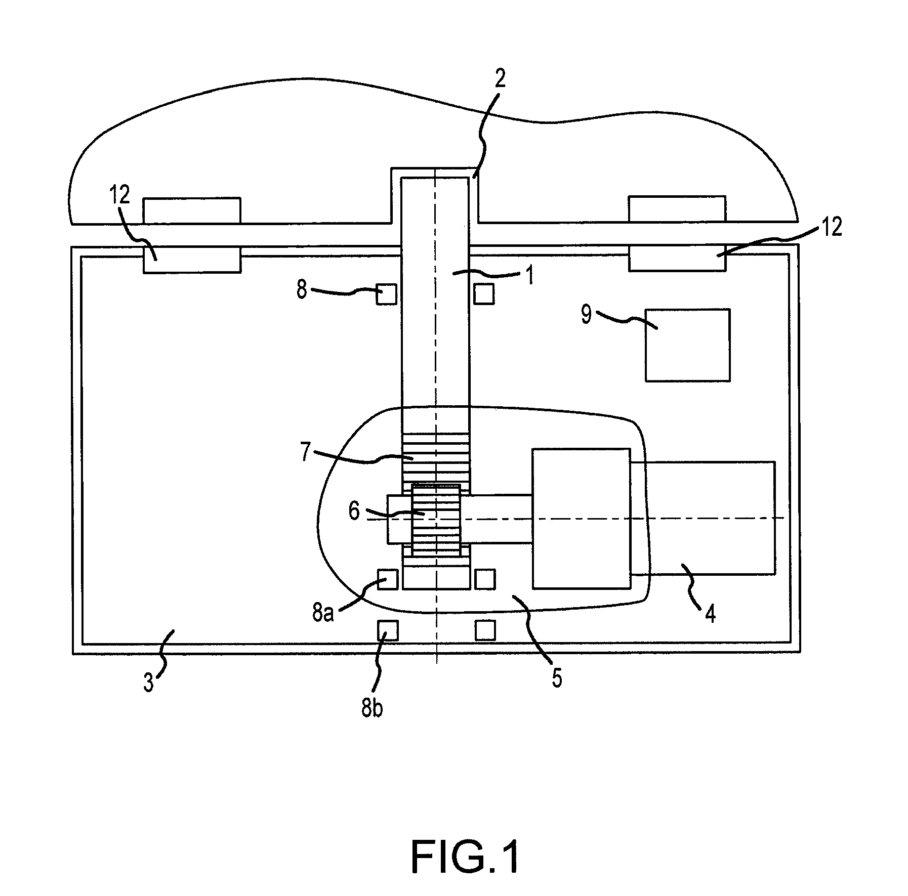
[0026]FIG. 1 shows a schematic of a guard lock according to the invention in an locking state. The door illustrated in the drawing, as movable part, can be held shut with respect to a fixed wall (not illustrated) as fixed part by a bolt 1 if the guard lock is fastened to one of the two parts and engages in a form-locking manner with the bolt 1 in a corresponding cutout 2 in the other part. The bolt 1 is located in an locking or blocking end position.

[0027]In the unlocked end position, the bolt 1 has been inserted substantially into the housing 3.

[0028]In the locking end position in FIG. 1, the bolt 1 has been withdrawn from the housing 3 and can lock the door. For this purpose the bolt 1 engages in the cutout 2 in the door or the wall in a form-locking manner depending on which of the two parts, i.e. the door or the wall, has been fitted with the guard lock.

[0029]The bolt 1 is guided movably in the bolt longitudinal direction. For driving the bolt 1, a drive 4 is provided, which can...


PUM


Abstract

Guard lock for a component for closing an opening having a fixed part and a movable part, with a bolt, which is guided movably between a locking and an unlocked end position in the longitudinal direction of the bolt, a drive implementing a movement for moving the bolt and a transmission device between the drive and the bolt, wherein the drive is an electric motor, and the drive, the transmission device and the bolt are coupled in terms of movement in such a way as to directly transfer kinetic energy, it being possible for the bolt speed to be regulated via a control, and it being possible for monitoring of the movement of the drive, which is coupled in terms of movement to the bolt, to be implemented by the control, and the control being connected to at least one sensor for determining the position of the movable part relative to the fixed part.

Description

[0001]The invention relates to a guard lock for a component for closing an opening in accordance with the preamble of claim 1.BACKGROUND OF THE INVENTION[0002]Guard locks are known as part of an access protection device for a closable area of a machine installation which may be the source of a potential hazard. The installation may be, for example, machines or components such as robots for manufacturing, treating or processing workpieces and chemical installations or the like.[0003]A guard lock is arranged between a door or shutter closing the area as movable part and opposing walls or a frame as fixed part. The at least one door or flap, which may be sealed around the periphery and which can be opened and closed by pivoting or sliding, can be arrested or locked by the guard lock.[0004]In each case at least one safety sensor is located between the door and the adjacent wall. In addition, a control is provided which is coupled to the machine installation and the safety sensor in orde...

Claims


Application Information

Patent Timeline
IPC IPC(8): G06F7/04B05C1/06
CPCE05B47/026F16P7/00E05B47/0012E05B2047/0016E05B2047/002E05B2047/0068E05B2047/0069E05B2047/0017Y10T292/1021
Inventor SPARENBERG, INGOWILTING, ANDREASCEVIK, YASARYU, YAOHERBOTE, MICHAEL
Owner K A SCHMERSAL HLDG
Learn More