Apparatus for separating oil well products

a technology for oil well products and accessories, applied in the direction of separation process, liquid displacement, borehole/well accessories, etc., can solve the problems of affecting the operation of the oil well, the separation process is not smooth, and the oil level or height of the oil well is not adjustable. , to achieve the effect of preventing re-entrainment, preventing tank overflow and oil spills, and preventing re-entrainmen

Active Publication Date: 2013-07-30
KBK IND
View PDF16 Cites 17 Cited by
  • Summary
  • Abstract
  • Description
  • Claims
  • Application Information

AI Technical Summary

Benefits of technology

[0020]A sixth feature is its oil conduit that prevents re-entrainment. The oil conduit is a pipe that extends from the lower surface of the inverted upper spreader and provides a direct route for oil separated beneath that spreader to enter the oil layer without being re-entrained in the inlet water turbulent zone where the inlet water, oil, and solids are entering the tank.
[0021]A seventh feature is its slide tube for the water leg. The slide tube allows the water leg to be effectively shortened or lengthened to allow for the interface to be adjusted without stopping the flow of fluid or shutting the separator down.
[0022]An eighth feature is its engineered water spillover weir that prevents separation upsets. By using the

Problems solved by technology

However, these separators have several problems or shortcomings.
One such problem is that most separators do not have any way to adjust the level or height of the oil-water interface within the separator tank in response to varying operational conditions.
Separators that have means for adjusting the height of the oil-water interface do not have a good and easy way to adjust the location or level of the oil-water interface without shutting down the separator.
Another problem has been that most separators are not designed to handle large slugs of oil or water, and when the capacity of those separators has been exceeded during upset times, oil spills have occurred.
Still another problem with prior separators is that the inlet connection has not been at or near ground level which makes connecting the separator to the production well or other source of fluid to be separated much more difficult, time consuming, expensive, and most importantly, quite dangerous.
Also any elevated connection is more difficult to service.
A further problem with prior separators has been that the concave side of the internal upper spreader has been oriented upward so that the spreader serves as a bowl for collecting solids.
Separation efficiency suffers.
This finally results in the need to shut the unit down, drain it and clean out the solids from the top of the bowl shaped internal upper spreader.
Still a further problem with prior separators is that they re-entrain separated oil

Method used


Image

  • Apparatus for separating oil well products
  • Apparatus for separating oil well products
  • Apparatus for separating oil well products

Examples


Embodiment Construction

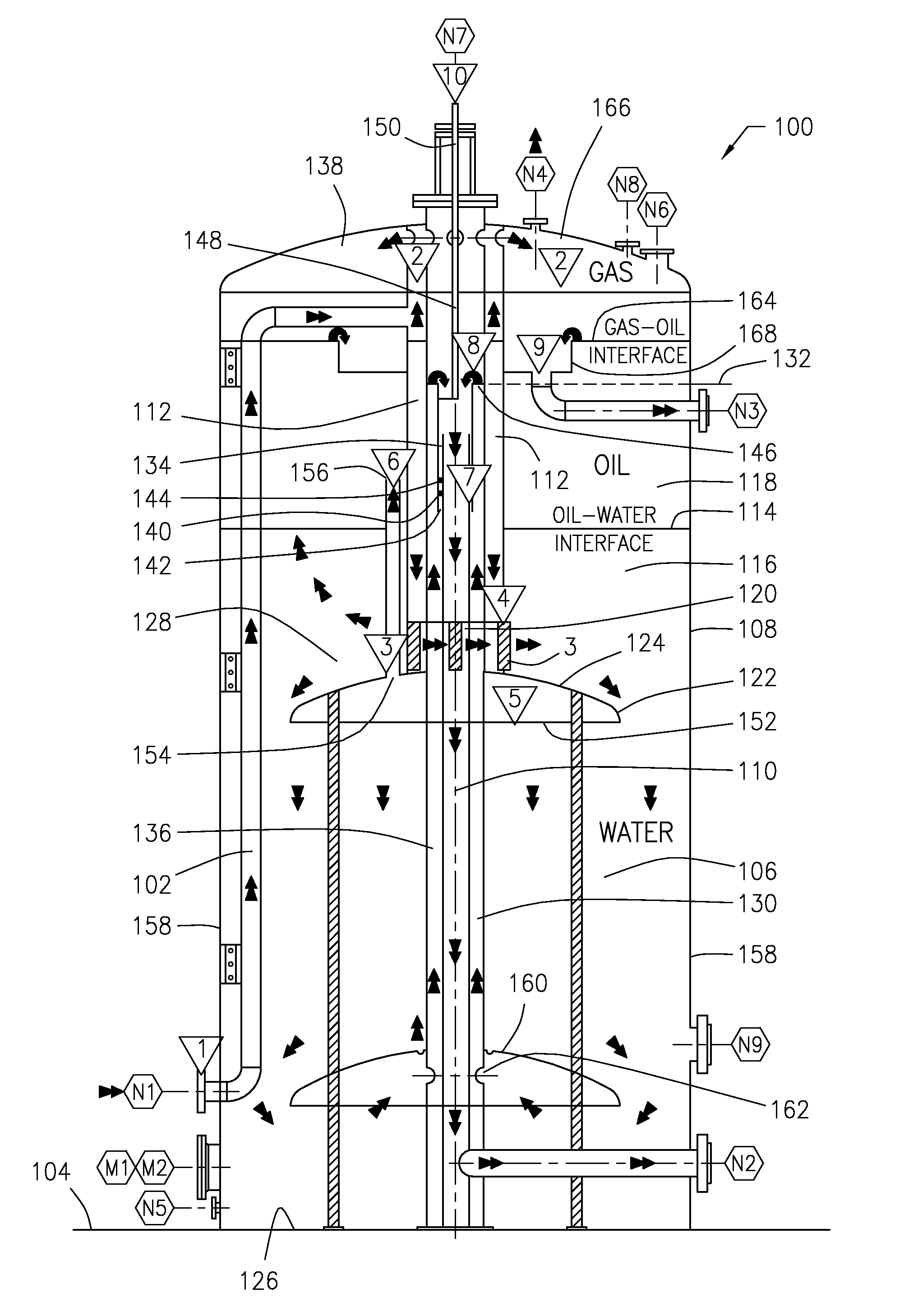
[0029]Referring now to FIG. 1, there is illustrated a separator apparatus 100 for separating oil well products. This is an atmospheric oil, water and gas separator 100 designed for separating applications such as those found in the oil field. Although the invention is described for use with oil field products, the invention is not so limited and could be used for other applications.

[0030]The separator 100 is a cylindrical tank or vessel 108 with an inlet 1 located near ground or grade level 104. The inlet 1 that admits the oil well products or fluids via inlet piping N1 into internal piping 102 contained within the tank 108. The fluids flow through the piping 102 and come to a center conduit 112 which extends upward into a degassing chamber 2 to which entrained gases in the fluid can rise. Gases that accumulate in the degassing chamber 2 exit the tank 108 via a gas outlet N4 provided in the top 138 of the tank 108. The center conduit 112 also extends downward to terminate at tank fl...


PUM

PropertyMeasurementUnit
Pressureaaaaaaaaaa
Heightaaaaaaaaaa

Abstract

An atmospheric oil, water and gas separator designed for oilfield applications having ground level inlet, internal water leg, internal piping, a degassing chamber, a horizontal inlet fluid swirl wing distributor that creates centrifugal spiraling of inlet fluids to slow and increase flow residence time, a horizontal swirl wing baffle above the inlet that minimizes oil re-entrainment by preventing turbulence at the oil-water interface, an inverted upper spreader that prevents solids plugging and performance deterioration, an oil conduit extending from the lower surface of the inverted upper spreader to the oil layer to prevent re-entrainment of separated oil in the inlet water turbulent zone, an externally adjustable slide tube for the water leg spillover weir tube, engineered water and oil spillover weirs that prevent separator upsets and overflows, and a water leg adjuster providing fine tuning of the height of the water leg from outside the vessel without shutdown.

Description

BACKGROUND OF THE INVENTION[0001]1. Field of the Invention[0002]The present invention is an apparatus for separating oil well products. More specifically, the invention is an atmospheric oil, water, solids, and gas separator designed for oilfield applications.[0003]2. Description of the Related Art[0004]Separators that are intended to separate oil, water, solids, and gas from a mixture, such as a mixture produced by an oil well, have been in use for years. One such separator was designed by the present inventor and is the subject of U.S. Pat. No. 5,073,266 which issued on Dec. 17, 1991 for an Apparatus for Separating Commingling Heavier and Lighter Immiscible Fluids. However, these separators have several problems or shortcomings.[0005]One such problem is that most separators do not have any way to adjust the level or height of the oil-water interface within the separator tank in response to varying operational conditions. The level of the interface is critical to efficient separati...

Claims


Application Information

Patent Timeline
IPC IPC(8): B01D19/00
CPCE21B43/34B01D17/0208
Inventor BALL, IV, WILL D.
Owner KBK IND
Why Eureka
Try Eureka