Electro-optical device and electronic equipment

a technology of optical devices and electronic equipment, applied in the manufacture of electric discharge tubes/lamps, lighting and heating apparatus, instruments, etc., can solve the problems of insufficient panel cracking, and difficult to correspond to current client's demand, so as to prevent floating of liquid crystal panels.

Active Publication Date: 2013-07-30
JAPAN DISPLAY WEST
View PDF10 Cites 20 Cited by
  • Summary
  • Abstract
  • Description
  • Claims
  • Application Information

AI Technical Summary

Benefits of technology

[0013]However, even if only the wiring substrate is pushed, it is sometimes insufficient with respect to the floating of the liquid crystal panel. In addition, in the structure pushing the liquid crystal panel, the rib or the like strongly pushes the liquid crystal panel at the time of impact during drop, which causes the panel to crack. In addition, although a configuration in which a rib or...

Problems solved by technology

However, even if only the wiring substrate is pushed, it is sometimes insufficient with respect to the floating of the liquid crystal panel.
In addition, in the structure pushing the liquid crystal panel, the rib or the like strongly pushes the liquid crystal panel at the time of impact during drop, which causes the panel to crack.
In addition, although a configuration in which a rib or the like pushes a polarization plate is also proposed, this configuration is effective for the floating of the liquid crystal panel, but th...

Method used


Image

  • Electro-optical device and electronic equipment
  • Electro-optical device and electronic equipment
  • Electro-optical device and electronic equipment

Examples


Embodiment Construction

[0047]Embodiments of the present application will be described below in detail with reference to the drawings.

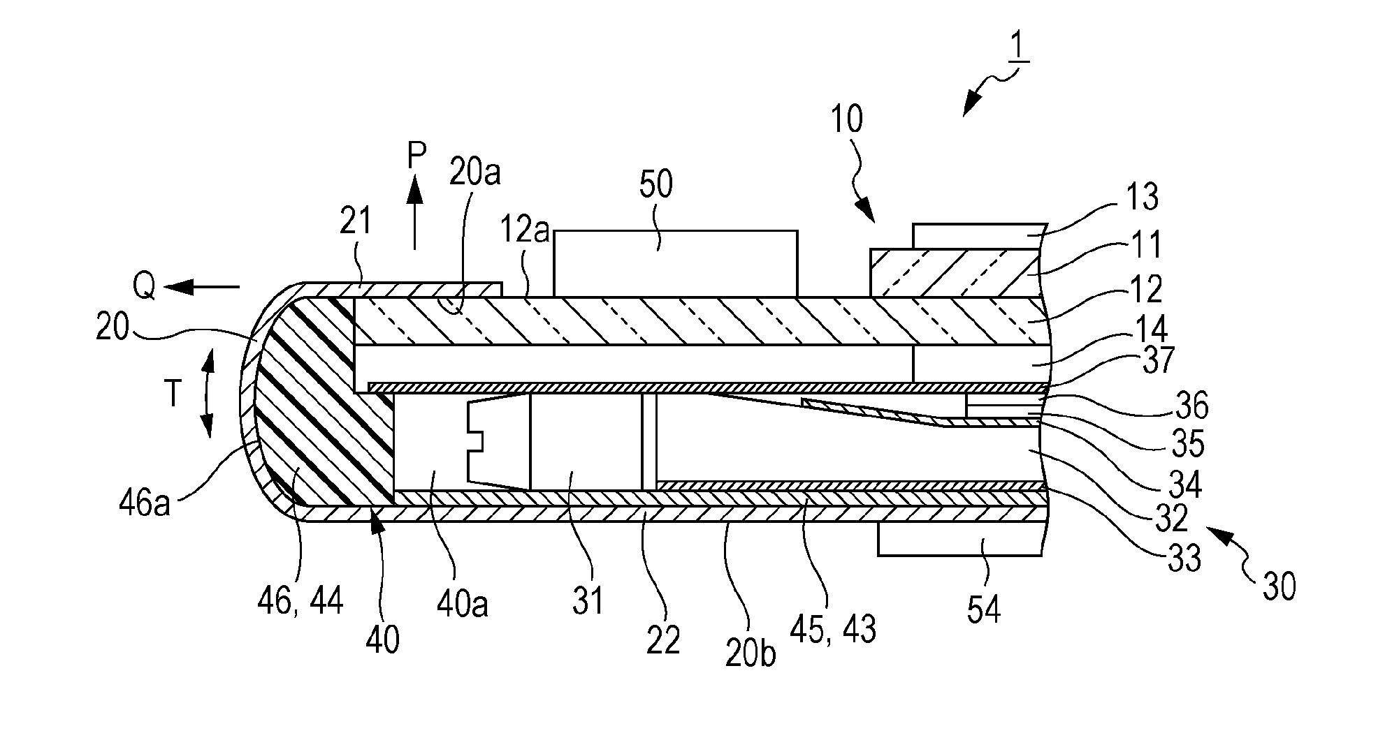
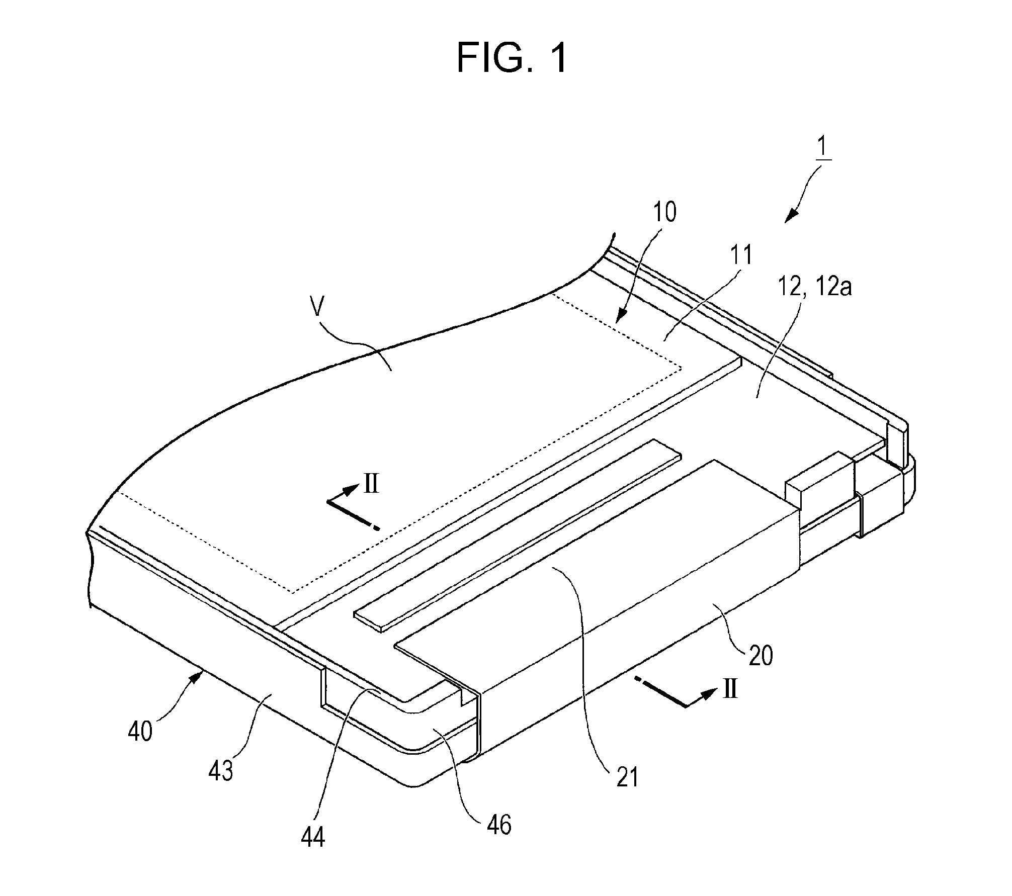
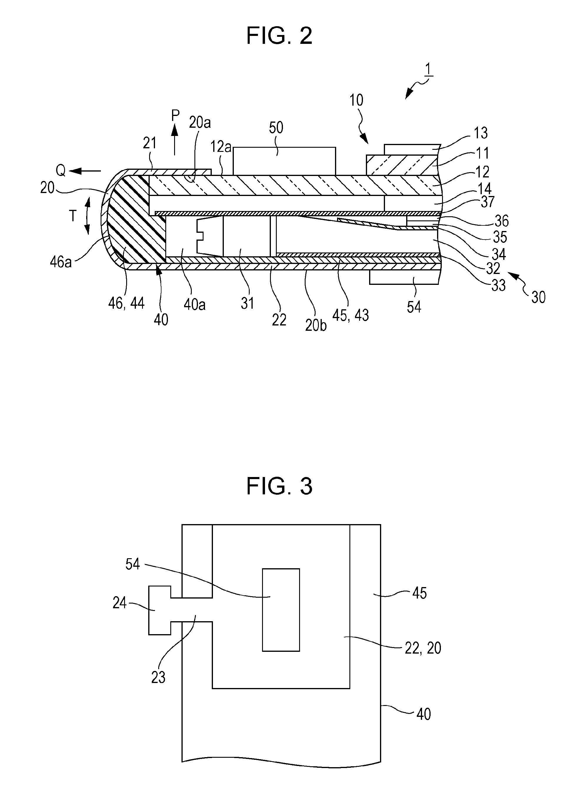
[0048]FIG. 1 is a principal part perspective view illustrating the specific configuration of a liquid crystal display device as an embodiment of an electro-optical device of the present application, FIG. 2 is cross-sectional view taken along the line II-II of FIG. 1 when viewed in the direction of the arrows, and FIG. 3 is a principal part bottom view of the liquid crystal display device (an electro optical device) shown in FIG. 1.

[0049]In theses drawings, reference numeral 1 is a liquid crystal display device (the electro-optical device). As shown in FIGS. 1 and 2, the liquid crystal display device 1 includes a liquid crystal panel (an electro-optical panel) 10, a FPC (Flexible Printed Circuit) substrate (a wiring substrate) 20 connected to the liquid crystal panel 10, an illumination device 30 for illustrating the liquid crystal panel 10, and a frame (an accommodation memb...


PUM


Abstract

An electro-optical device includes an electro-optical panel having a display surface; an accommodation member having a side wall that accommodates the electro-optical panel; and a wiring substrate with an end portion thereof connected to the electro-optical panel, wherein the other end portion side of the wiring substrate is bent to the opposite side of the display surface of the electro-optical panel, wherein the other end portion side of the wiring substrate is bent in the state of coming into close-contact with the side wall of the accommodation member and is fixed to the accommodation member or an accommodation object member that is accommodated in the accommodation member, and wherein the wiring substrate is in close-contact with the side wall of the accommodation member in the state in which a tension acts between the one end portion side and the other end portion side.

Description

CROSS REFERENCES TO RELATED APPLICATIONS[0001]The present application claims priority to Japanese Priority Patent Application JP 2009-290164 filed in the Japan Patent Office on Dec. 22, 2009, the entire contents of which are hereby incorporated by reference.BACKGROUND[0002]The present application relates to an electro-optical device and electronic equipment.[0003]Recently, in various types of electronic equipment, such as mobile phones or portable information terminals, a liquid crystal display device is used as a display portion for visually displaying various types of information.[0004]As an example of the liquid crystal display device, there is disclosed a liquid crystal display device that includes a liquid crystal panel which is an example of a display panel, a backlight (an illumination device), and a frame for accommodating the liquid crystal panel and the backlight.[0005]The liquid crystal panel is configured to have a pair of substrates, a seal material formed between the p...

Claims


Application Information

Patent Timeline
IPC IPC(8): G02F1/1333
CPCG02F1/133308G02F2201/46
Inventor KOBAYASHI, YOJI
Owner JAPAN DISPLAY WEST
Why Eureka
Try Eureka