Optical filter, optical filter module, spectrometric measurement apparatus, and optical apparatus
a filter module and optical filter technology, applied in the direction of optical radiation measurement, instruments, spectrometry/spectrophotometry/monochromators, etc., can solve the problems of overshooting (and undershooting) phenomena that occur when the voltages are applied in different cycles, and the variable wavelength filter cannot scan the entire desired wavelength band in a long time, so as to achieve excellent usability, wide wavelength range, and simplified configuration
- Summary
- Abstract
- Description
- Claims
- Application Information
AI Technical Summary
Benefits of technology
Problems solved by technology
Method used
Image

Examples
first embodiment
[0045]In a first embodiment, an example of the configuration and action of an optical filter (including a plurality of variable wavelength bandpass filters) will be described with reference to an optical apparatus (spectrometric measurement apparatus in the following description) including the optical filter. Examples of the spectrometric measurement apparatus may include a colorimeter, a spectrometric analysis apparatus, and an optical spectrum analyzer.
Example of Overall Configuration of Spectrometric Measurement Apparatus and Example of Configuration of Optical Filter
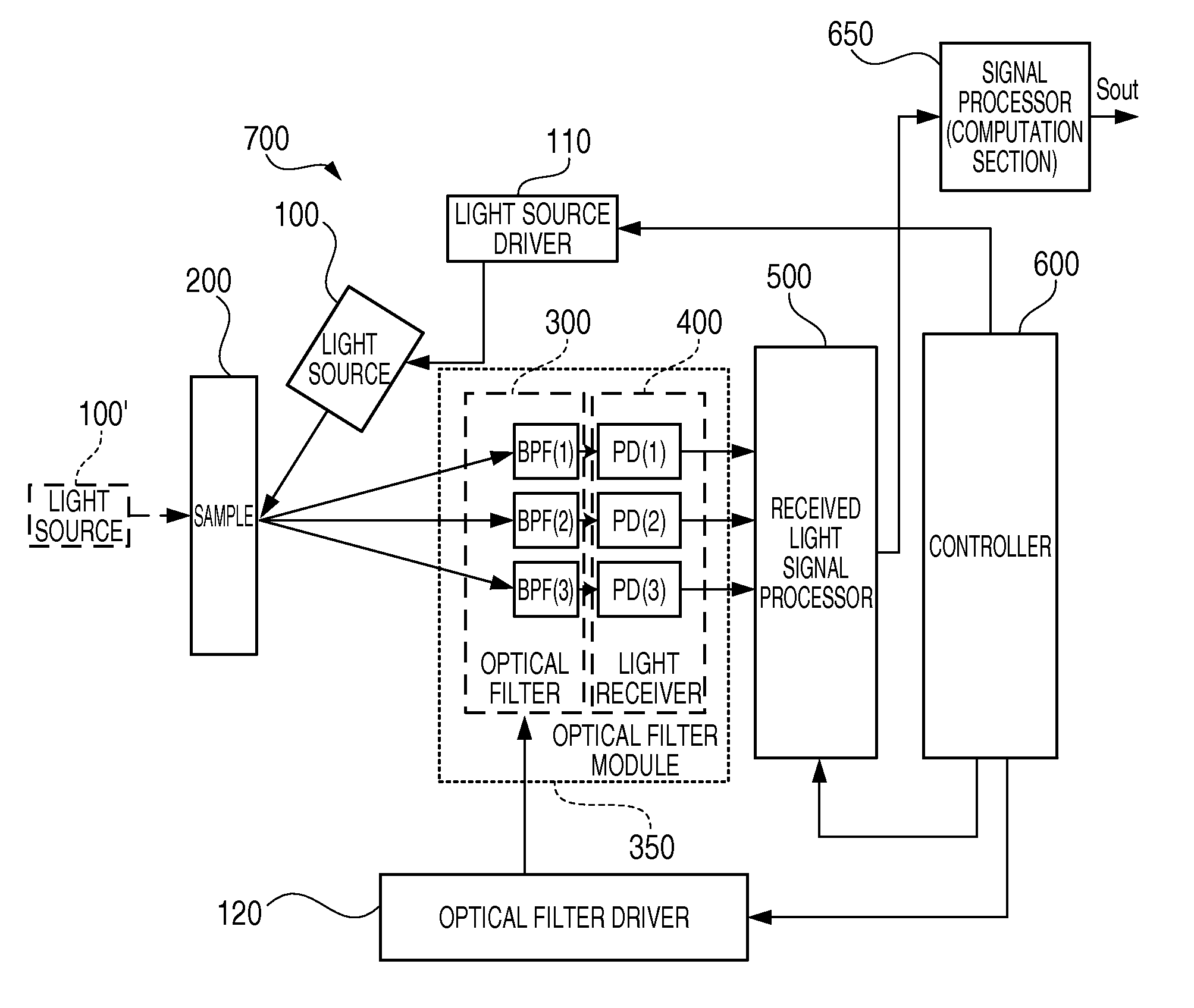
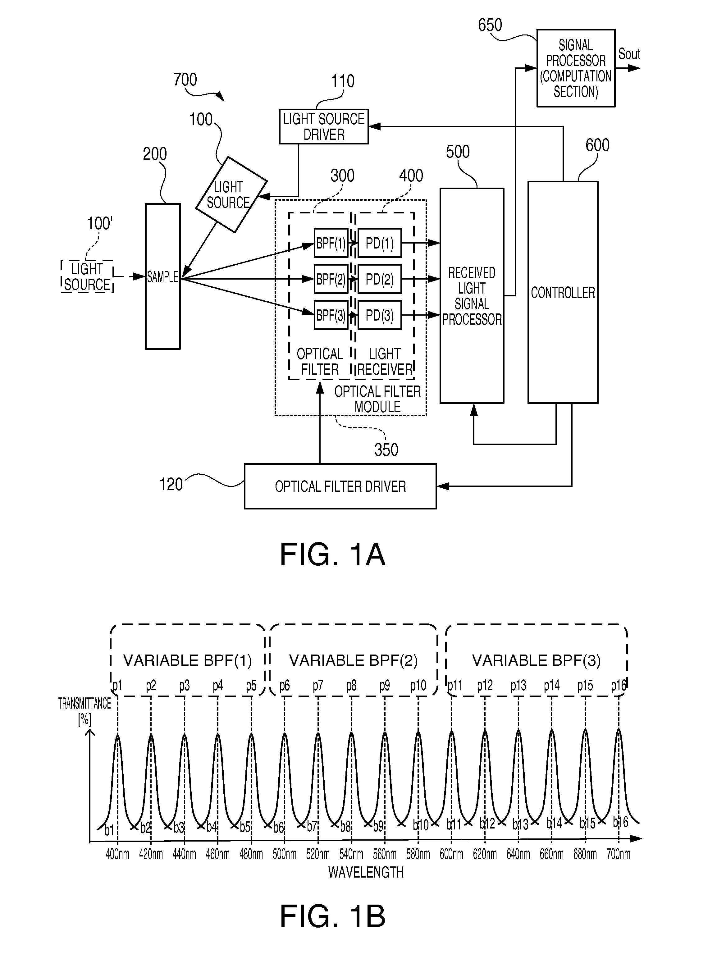
[0046]FIG. 1A shows an example of the overall configuration of a spectrometric measurement apparatus, and FIG. 1B shows an example of the configuration of an optical filter. For example, a light source 100 is used when the color of a sample 200 is measured, in which case, the light reflected off the sample 200 is incident on the optical filter. A light source 100′ is used when the sample 200 is analyzed spectrometric...
second embodiment
[0106]In a second embodiment, a specific method for driving variable gap etalon filters will be described. There are two methods for driving variable gap etalon filters: a method in which the filters have the same initial gap size and the drive voltages applied to the filters have different levels (first driving method) and a method in which the filters have different initial gap sizes and the same drive voltage is applied to the filters (second driving method). The two methods will be described below in this order.
First Driving Method
[0107]FIG. 10 describes the first driving method for driving variable gap etalon filters. As shown in an upper portion of FIG. 10, three variable gap etalon filters 10A, 10B, and 10C are arranged side by side.
[0108]The filters 10A, 10B, and 10C have the same initial gap size G10. The filters 10A, 10B, and 10C correspond to the variable wavelength bandpass filters BPF(1) to BPF(3) shown in FIG. 1A. Each of the filters 10A, 10B, and 10C has the structure...
third embodiment
[0124]FIG. 13 is a block diagram showing a schematic configuration of a transmitter in a wavelength multiplexing communication system, which is another example of the optical apparatus according to an embodiment of the invention. Wavelength division multiplexing (WDM) communication is based on the fact that signals having different wavelengths do not interfere with each other. When a plurality of optical signals having different wavelengths are multiplexed in a single optical fiber, the amount of transmitted data can be increased without any increase in the number of optical fiber communication lines.
[0125]In FIG. 13, a wavelength multiplexing transmitter 800 includes an optical filter 300 on which light from a light source 100 is incident, and a plurality of light fluxes of wavelengths λ0, λ1, λ2, and so on are outputted from the optical filter 300. Transmission devices 311, 312, and 313 are provided for the respective wavelengths. Optical pulse signals corresponding to a plurality...
PUM
| Property | Measurement | Unit |
|---|---|---|
| wavelength band | aaaaa | aaaaa |
| wavelength band | aaaaa | aaaaa |
| wavelength band | aaaaa | aaaaa |
Abstract
Description
Claims
Application Information
PatSnap Eureka turns technology decisions into work you can execute. Powered by our Innovation Knowledge Graph, it runs expert workflows across engineering, life sciences, materials and intellectual property. Get your review-ready output in minutes.


