Deposit removing device

a deposit removal and deposit technology, applied in the direction of cleaning equipment, lighting and heating apparatus, cleaning using liquids, etc., can solve the problems of reducing the spacing distance, the coefficient between the contact surfaces, and the plate-like member itself bursting, so as to reduce the spacing distance and efficiently remove the deposit

Inactive Publication Date: 2013-08-06
KOBE STEEL LTD
View PDF42 Cites 5 Cited by
  • Summary
  • Abstract
  • Description
  • Claims
  • Application Information

AI Technical Summary

Benefits of technology

[0013]The present invention has been made in view of the above-described circumstances, and the object thereof is to provide a deposit removing device capable of efficiently removing deposit on the plate-like member such as a metal plate by reducing the spacing distance between the plate-like member and the injection nozzle, and also capable of coping with the removal of deposit on the plate-like member rolled or conveyed at a high speed.
[0014]The present invention is incorporated into the deposit removing device that removes deposit adhered to the plate-like member by jetting compressed gas from a jetting hole of a nozzle body in which the jetting hole is formed. This deposit removing device is configured so that the nozzle body is supported so as to be movable in a direction substantially perpendicular to the surfaces of the plate-like member. By causing the nozzle body to follow undulations of the plate-like member and moving it, it is possible to maintain the nozzle body in a state of being always spaced apart from the plate-like member by a substantially fixed distance.

Problems solved by technology

This is because, if the plate-like member is rolled up with the rolling oil adhered thereto, the friction coefficient between the contact surfaces between plate-like member portions that have been rolled up decreases, so that there arises a problem in that the plate-like member may slide sideways along the direction of its width to thereby collide against the rolling-up device, or the plate-like member itself may rupture.
Also, if the plate-like member (rolling coil) that has been rolled up with the rolling oil unsatisfactorily removed, is annealed at a subsequent process, there may occur a problem of causing local nonuniformity in annealing result, leading to a reduction in product quality.
Furthermore, if the plate-like member is stored with the cleaning liquid adhered thereto, there may arise a problem of the plate-like member being corroded by the cleaning liquid.
However, since the above-described method for removing deposit using the rubber wiper or one of the pair of rollers makes the roller pair and the plate-like member contact with each other, there is a possibility that contact damage such as scratches may occur on the surfaces of the plate-like member.
Especially when the pair of rubber rollers or pair of steel rollers is used, the deposit removing effect increases as the pressing force on the plate-like member increases, but on the other hand, the plate-like member becomes more susceptible to the contact damage.
Such a problem becomes more serious as the plate-like member becomes thinner, and in some cases, it may lead to even rupture of the plate-like member.
However, not only the deposit removing effect is reduced by hole clogging on the roller surface, but also there is inconvenience of having to perform maintenance work for eliminating hole logging.
However, because a jetting nozzle and the surface of a rolled plate are arranged apart from each other by about several millimeters to several tens of millimeters, there is a problem in that the jetting energy (jetting pressure) of air is dispersed and a sufficient deposit removing effect cannot be obtained.
Of course, if the compression pressure of compressed air to be supplied to the jetting nozzle is set to a higher pressure, the deposit removing effect would be enhanced, but the compressor for producing compressed air, air tank for storing compressed air or the like is upsized, and further, air piping and the like is forced to have a high resistance, which is undesirable from economical and practical viewpoints.
However, if the jetting nozzle is brought too close to the surface of the plate-like member, there occurs a possibility that the plate-like member may be damaged from vibrations during rolling, vibrations during the conveyance of the plate-like member, or warpage of the plate-like member.
For this reason, it has hitherto been difficult to bring the jetting nozzle close to the surface of the rolled plate within a range of several millimeters.
In recent years, in which the rolling speed (conveying speed) is becoming increasingly faster (about 800 m / min or more), even if any one of the above-described deposit removing methods is used, it would be impossible to efficiently and effectively remove deposit on the plate-like member rolled or conveyed at a high speed.

Method used


Image

  • Deposit removing device
  • Deposit removing device
  • Deposit removing device

Examples


example 1

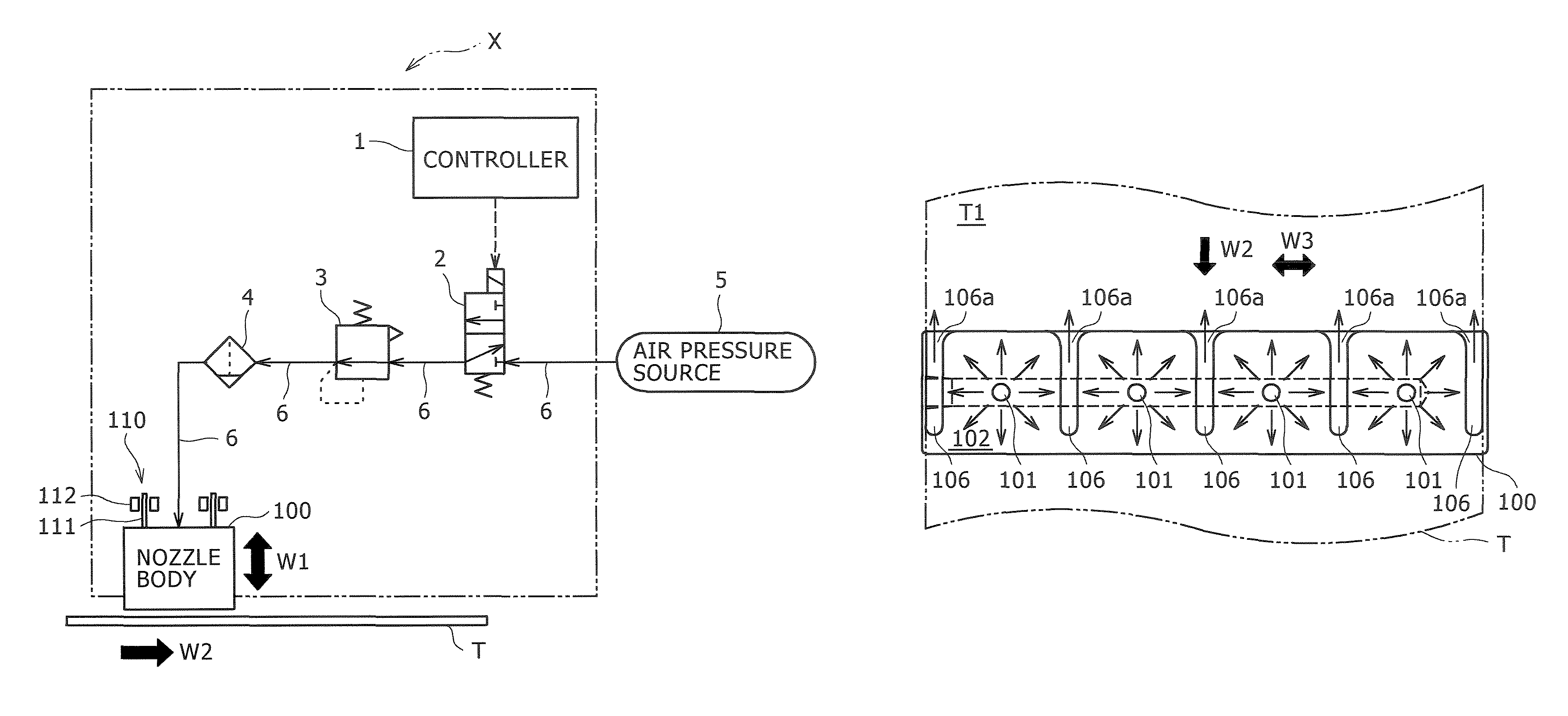
[0074]Next, a deposit removing device X1 according to an example 1 of the present invention will be described with reference to FIGS. 11 and 12. FIG. 11 is a schematic longitudinal sectional view of the nozzle body 100a, and FIG. 12 is an arrow view of the nozzle body shown in FIG. 11. The same components as those in the above-described embodiment are designated by the same symbols, and descriptions thereof are omitted.

[0075]The deposit removing device X1 according to this embodiment is embodied into the deposit removing device X of the above-described embodiment in that, as shown in FIG. 11, and notably in FIG. 12, the deposit removing device X1 uses a nozzle body 100a in which the opposed surface 102 facing the top surface T1 has a groove 107. Although, in FIG. 11, grooves 106 (refer to FIGS. 2 to 4) formed in the nozzle body 100 are not shown, the nozzle body 100a may include the grooves 106.

[0076]As shown in FIG. 11, the groove 107 is formed in the direction perpendicular to the...

example 2

[0077]Next, a deposit removing device X2 according to an example 2 of the present invention will be described with reference to FIGS. 13 and 14.

[0078]In this example, a nozzle body 100b shown in FIG. 13 is used. In the nozzle body 100b of the deposit removing device X2, in its opposed surface, there are provided four jetting ports 101 that are arranged at spacings along the direction W3 substantially perpendicular to the conveying direction W2 of the plate-like member T (refer to FIG. 13) of the plate-like member T and the moving direction W1 (refer to FIG. 14) of the nozzle body 100b; and further, jetting port train 101b substantially same as a jetting port train 101a in a group of the above-described four jetting ports are arranged in parallel with the jetting port train 101a at predetermined spacings on the downstream side in the conveying direction W2. By juxtaposing such jetting port train 101a and jetting port train 101b, even when deposit that could not removed by the jetting...

example 3

[0084]Next, an example 3 will be described with reference to FIG. 15 (block diagram). A deposit removing device X3 according to this example is constructed to include the air release hole 109b provided in the nozzle body 100b (example 2, refer to FIG. 13); an oil separator 120 (one example of deposit separating / recovering means) that separates liquid or misty rolling liquid (one example of liquid deposit) contained in the air discharged from the air release hole 109b, from the air, and that recovers it in an oil tank 130 arranged outside the device; an injector 122 for guiding the separated rolling oil to the oil tank 130. Because other components of the deposit removing device X3 is similar to those of the deposit removing device X2, description thereof herein is omitted.

[0085]Possible types of the oil separator include various ones, but here, a device is exemplified that has therein an oil filter 120a for separating rolling oil alone from air, and that has a drain layer 120b with ...


PUM

PropertyMeasurementUnit
distanceaaaaaaaaaa
distanceaaaaaaaaaa
areaaaaaaaaaaa

Abstract

A deposit removing device capable of efficiently removing deposit on a plate-like member such as a metal plate or resin plate by reducing a spacing distance between the plate-like member and an injection nozzle, and also capable of coping with the removal of deposit on the plate-like member rolled or conveyed at a high speed. This deposit removing device removes the deposit adhered to the plate-like member (T) by jetting compressed air from at least one jetting hole (101) of a nozzle body (100) in which the at least one jetting hole (101) is formed. This device is configured so that the nozzle body (100) is supported so as to be movable in a direction (W1) substantially perpendicular to the surfaces (T1 and T2) of the plate-like member (T).

Description

TECHNICAL FIELD[0001]The present invention relates to a deposit removing device for removing an oil component such as rolling oil adhered to a plate-like member and / or a liquid such as a cleaning liquid for cleaning the plate-like member. More specifically, the present invention relates to a deposit removing device for removing the above-described deposit by blowing compressed air on the plate-like member.BACKGROUND ART[0002]In general, when rolling a metal plate or resin plate by a rolling machine, rolling oil is supplied to a rolling contact portion between a work roll (mill roll) and the plate-like member, in order to cool the work roll or the plate-like member rolled by the work roll, or to improve rolling efficiency. Also, when it is necessary to clean soils or oxide films off the surfaces of the plate-like member, the plate-like member is passed through a cleaning tank that contains cleaning liquid.[0003]Since the rolling oil and / or cleaning liquid thus adheres to the plate-li...

Claims


Application Information

Patent Timeline
Patent Type & Authority Patents(United States)
IPC IPC(8): B08B5/00
CPCB08B5/026B21B45/0278C23G5/00B21B45/0233B21B45/0284
Inventor YOSHIMURA, SHOJIUESUGI, KENICHIMIYAZONO, TAISUKEHONKE, KOICHIOKADA, TORU
Owner KOBE STEEL LTD
Why Eureka
Try Eureka