Dewpoint cooling device

a cooling device and airflow technology, applied in the field of devices for cooling airflow, can solve problems such as the decrease of temperature in the cooling channel, and achieve the effect of pleasing the indoor clima

Inactive Publication Date: 2013-08-06
OPTIMAIR HLDG
View PDF20 Cites 24 Cited by
  • Summary
  • Abstract
  • Description
  • Claims
  • Application Information

AI Technical Summary

Benefits of technology

[0007]The invention now has for its object to improve a cooling device of the above described type such that the supplied airflow can be cooled still further therewith, and an even more pleasant indoor climate can be realized. According to the invention this is achieved in such a cooling device by means for dehumidifying the airflow in the cooling channel. By extracting moisture from the air for cooling, this air can absorb more moisture in the evaporating channel, whereby a larger quantity of evaporation heat is extracted from the wall and the temperature thereof thus decreases further.
[0012]In a structurally and operationally simple embodiment of the cooling device the regenerating means are adapted to periodically heat the LCST polymer above the critical solution temperature. Since such a polymer is characterized by its low critical solution temperature, usually in the order of 60 to 70° C., simple heating elements can suffice.

Problems solved by technology

Due to the good heat conduction of the transfer walls, this also results in a temperature decrease in the cooling channels, whereby the airflow is thus cooled.

Method used


Image

  • Dewpoint cooling device
  • Dewpoint cooling device
  • Dewpoint cooling device

Examples


Embodiment Construction

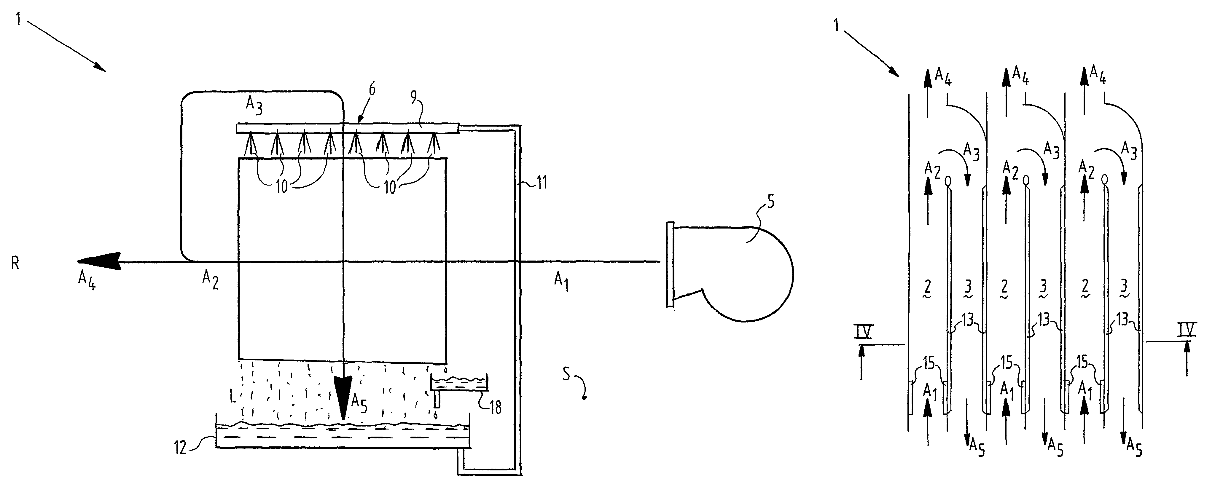
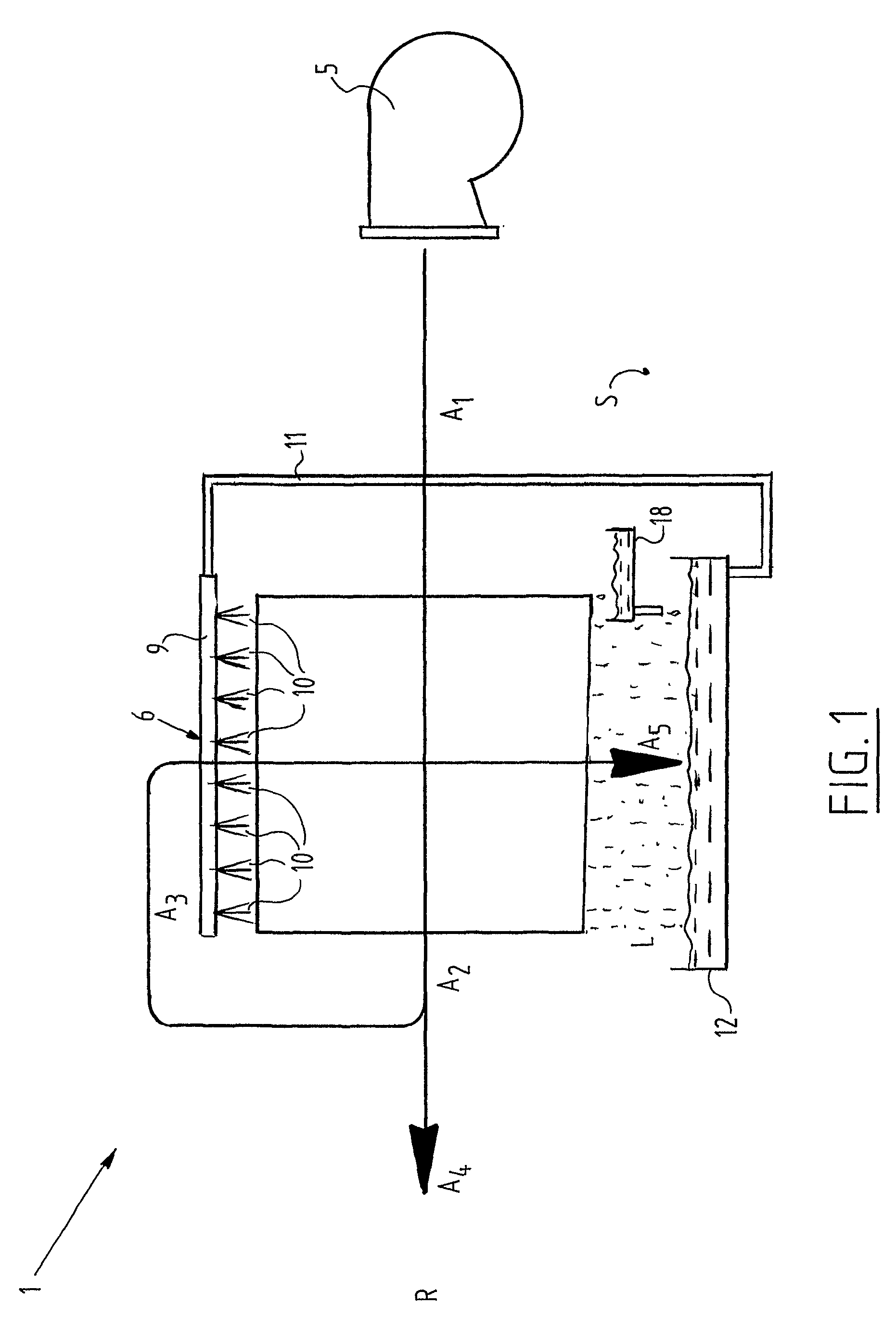
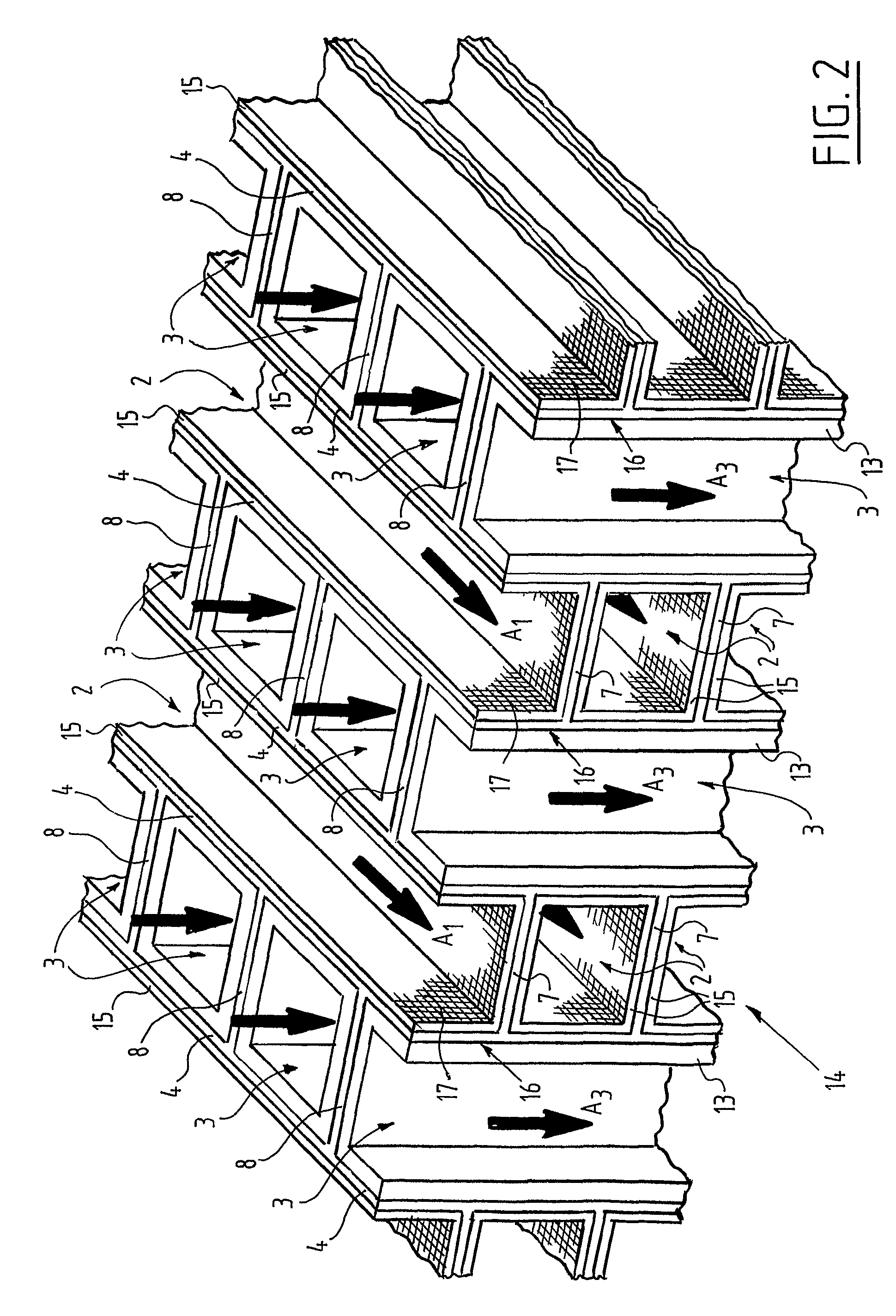
[0020]A device 1 (FIG. 1) for cooling an airflow comprises a number of groups of mutually parallel cooling channels 2 separated by partition walls 7 (FIG. 2), with an inflow opening for the airflow A1 for cooling and an outflow opening for the cooled airflow A2. The inflow openings are for instance connected to the outside environment S, while the outflow openings debouch into a space for cooling R. The airflow through cooling device 1 is provided by a fan 5.

[0021]Cooling device 1 further comprises a number of groups of evaporating channels 3 separated from cooling channels 2 by transfer walls 4. Evaporating channels 3 are mutually separated by partition walls 8. The inflow openings of evaporating channels 3 are connected to the outflow openings of cooling channels 2, while the outflow openings of cooling channels 3 debouch into the outside environment S.

[0022]Due to the connection between cooling channels 2 and evaporating channels 3 a partial flow A3 is separated from cooled airfl...


PUM


Abstract

Airflow cooling device including a cooling channel, an evaporating channel separated from the cooling channel by a transfer wall, outflow from the cooling channel going to the evaporating channel, and a lower critical solution temperature polymer at least partially covering the cooling channel side of the transfer wall.

Description

TECHNICAL FIELD[0001]The invention relates to a device for cooling an airflow, comprising at least one cooling channel with an inflow opening for the airflow for cooling and an outflow opening for the cooled airflow, at least one evaporating channel separated from the cooling channel by a transfer wall and having an inflow opening, which is connected to the outflow opening of the cooling channel, and an outflow opening, and means for wetting the side of the transfer wall directed toward the evaporating channel. Such a device, with which an airflow can be cooled indirectly by means of evaporation and which is also referred to as “dewpoint cooler”, is known from American U.S. Pat. No. 4,002,040.BACKGROUND ART[0002]The known cooling device takes the form of a crosscurrent heat exchanger with a number of groups of mutually parallel cooling channels and a number of groups of evaporating channels which are likewise mutually parallel and which run perpendicularly of the cooling channels. A...

Claims


Application Information

Patent Timeline
Patent Type & Authority Patents(United States)
IPC IPC(8): F28D5/00F28D5/02F28C1/00F24F1/0071
CPCF24F5/0035F28D5/02Y02B30/545F24F2001/0092F24F1/0007Y02B30/54F24F1/0071F24F5/00
Inventor MEIJER, WILLEM
Owner OPTIMAIR HLDG
Why Eureka
Try Eureka