Phase shift controller

a technology of phase shift controller and driving circuit, which is applied in the direction of electric variable regulation, process and machine control, instruments, etc., to achieve the effect of simple manner

Active Publication Date: 2013-08-06
ROHM CO LTD
View PDF5 Cites 5 Cited by
  • Summary
  • Abstract
  • Description
  • Claims
  • Application Information

AI Technical Summary

Benefits of technology

[0014]The present invention has been made in order to solve such a problem. Accordingly, it is an exemplary purpose of an embodiment of the present invention to provide a circuit which is capable of providing a phase shift burst dimming operation in a simple manner.
[0016]Such an embodiment requires only a single dimming pulse signal to automatically generate a burst control signal for each channel by means of the phase shift controller. Thus, there is no need to employ an external processor to generate a signal for each channel, thereby facilitating system design. Furthermore, such an arrangement requires only two counters in the phase shift controller. Thus, such an arrangement provides a reduced circuit area as compared with a circuit including a counter for each channel.
[0018]Such an arrangement is capable of preventing the dimming pulse signal from remaining at a first level even if the duty ratio of the dimming pulse signal suddenly becomes smaller.
[0022]With such an embodiment, the collector-emitter voltage of the output transistor is reduced by the voltage drop that occurs at the heat dissipation resistor. Thus, such an arrangement is capable of reducing power consumption of the output transistor, i.e., of reducing its heat generation.

Problems solved by technology

Furthermore, such an arrangement requires only two counters in the phase shift controller.

Method used


Image

  • Phase shift controller
  • Phase shift controller
  • Phase shift controller

Examples


first embodiment

[First Embodiment]

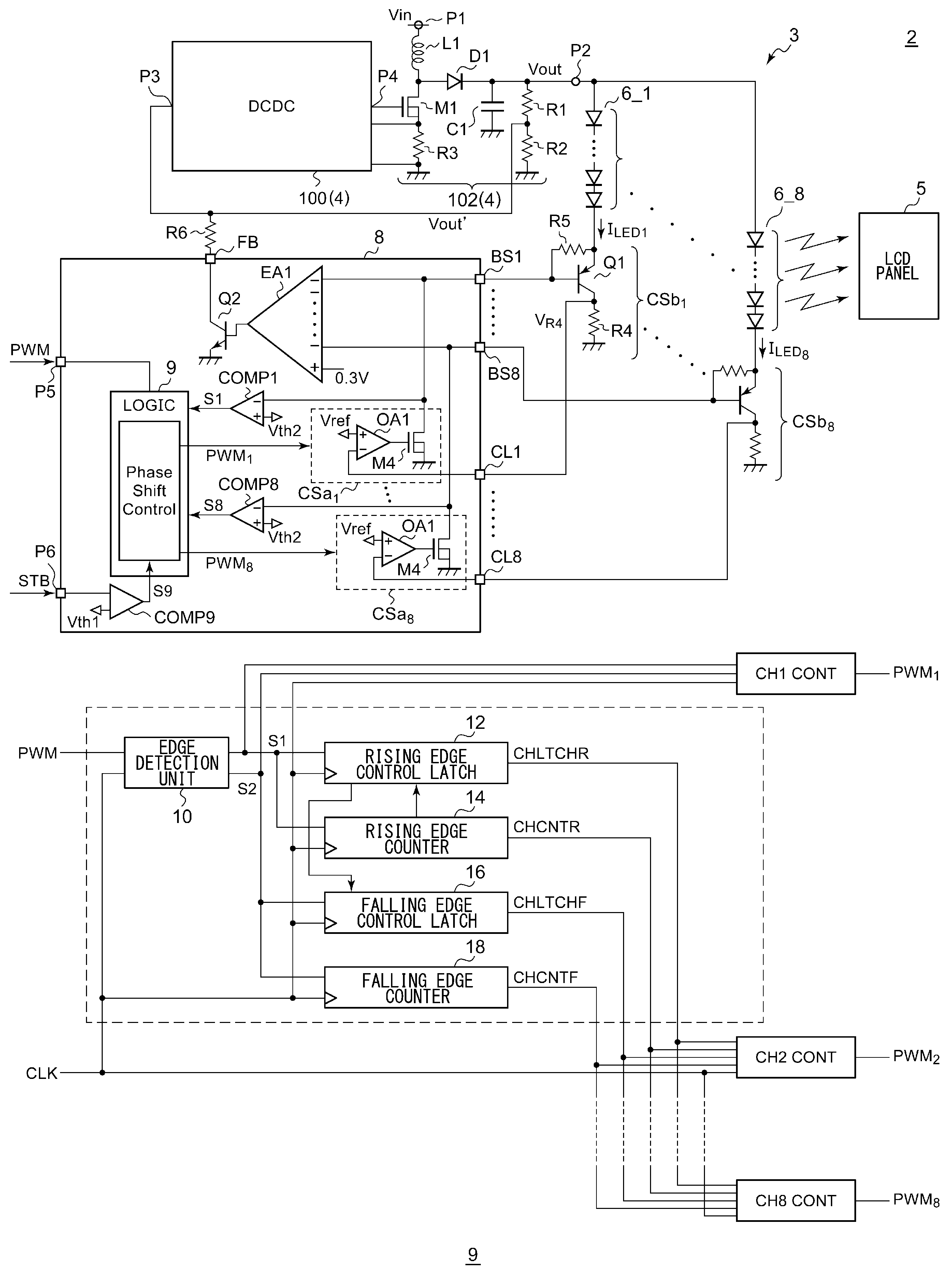
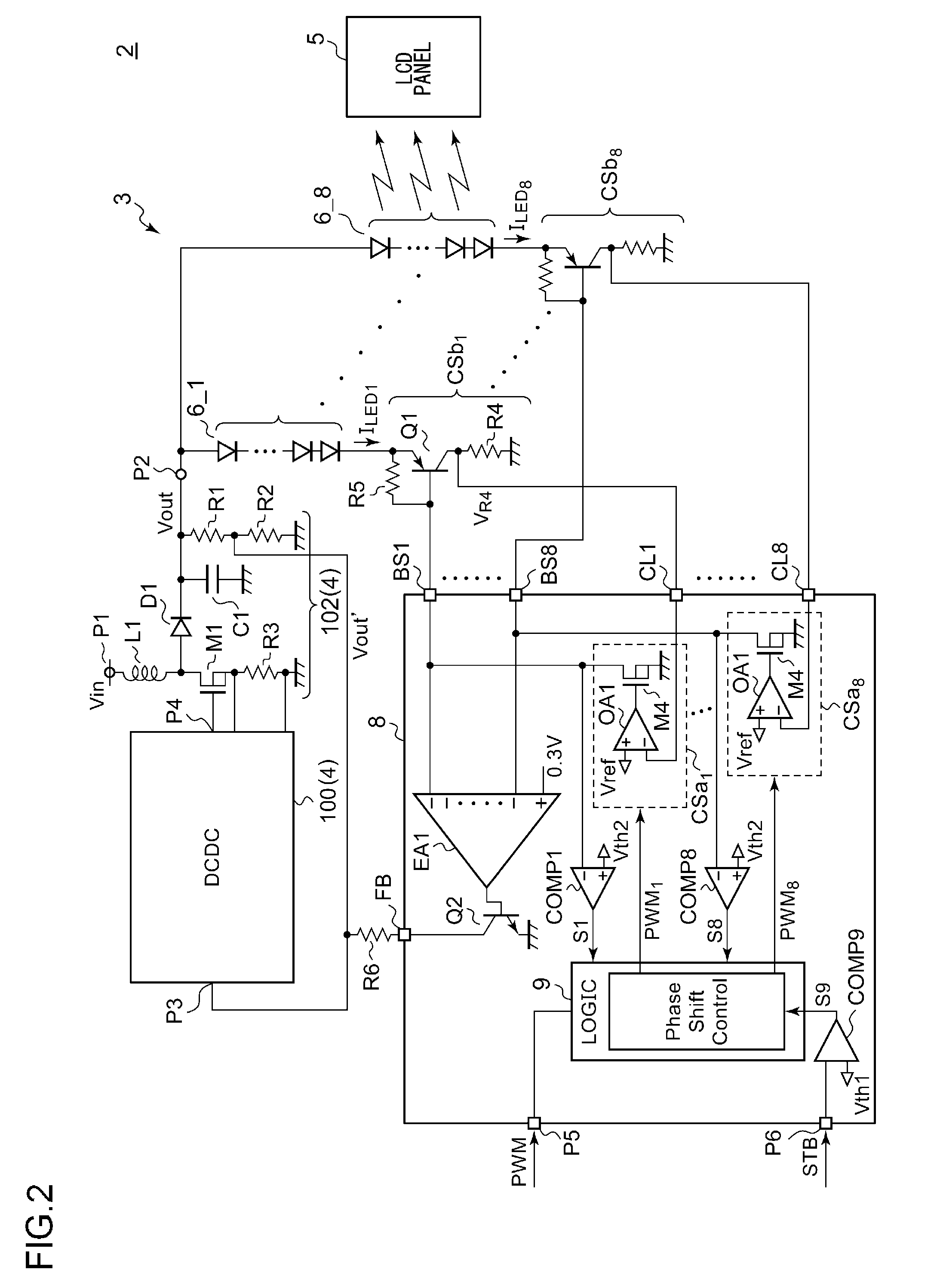
[0043]FIG. 2 is a circuit diagram which shows a configuration of an electronic device including a switching power supply according to a first embodiment.

[0044]An electronic device 2 is configured as a battery-driven device such as a laptop PC, a digital still camera, a digital video camera, a cellular phone terminal, a PDA (Personal Digital Assistant), or the like. The electronic device 2 includes a light emitting apparatus 3 and an LCD (Liquid Crystal Display) panel 5. The light emitting apparatus 3 is arranged as a backlight of the LCD panel 5.

[0045]The light emitting apparatus 3 includes LED strings 6_1 through 6_8 each configured as a light emitting element, a current driving circuit 8, and a switching power supply 4. There is a maximum number of n (eight) effective channels, and the number of channels is determined by the designer of the electronic device based on the size of the LCD panel 5, the kind of electronic device 2, etc. That is to say, the number of ...

second embodiment

[Second Embodiment]

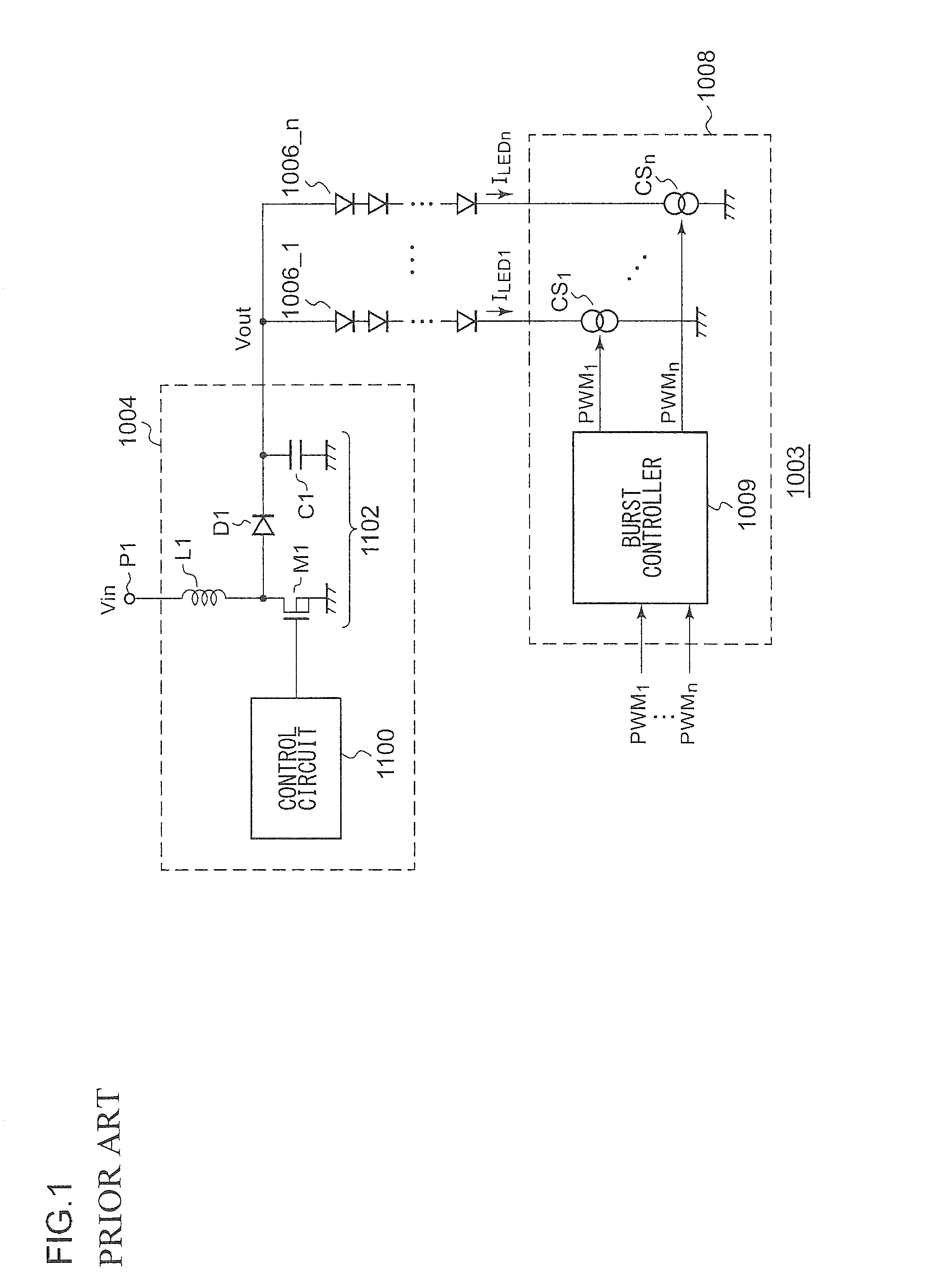
[0114]In recent years, as a backlight of a liquid crystal panel or an illumination device, a light emitting apparatus using an LED (light emitting diode) is employed. FIG. 8 is a circuit diagram which shows a configuration of a light emitting apparatus investigated by the present inventor. A light emitting apparatus 1003 includes an LED string 1006, a switching power supply 1004, and a current source CS.

[0115]The LED string 1006 includes multiple LEDs connected in series. The switching power supply 1004 boosts an input voltage Vin so as to supply a driving voltage Vout to one terminal of the LED string 1006.

[0116]The current source CS is arranged on a path of the LED string 1006. The current source CS supplies a driving current ILED to the corresponding LED string 1006 according to the target luminance level. The current source CS includes an output transistor Q1, a current control resistor R4, and an operational amplifier OA. The output transistor Q1 is configure...


PUM


Abstract

A positive counter starts counting, starting with an initial value, upon receiving a positive edge of a dimming pulse signal. A negative edge counter starts counting, starting with an initial value, upon receiving a negative edge of the dimming pulse signal. For each i-th (2≦i≦n) channel, the phase shift amount is calculated by multiplying a period count value that indicates the period of the dimming pulse signal by (i−1) / n. When the count value matches the phase shift amount, a burst control signal is switched to a first level. When the count value matches the phase shift amount, the burst control signal is switched to a second level.

Description

BACKGROUND OF THE INVENTION[0001]1. Field of the Invention[0002]The present invention relates to a driving circuit for a light emitting diode.[0003]2. Description of the Related Art[0004]In recent years, as a backlight of a liquid crystal panel or as an illumination device, a light emitting apparatus is employed, which is configured using an LED (light emitting diode). FIG. 1 is a circuit diagram which shows a typical configuration of a light emitting apparatus. A light emitting apparatus 1003 includes multiple LED strings 1006_1 through 1006_n, a switching power supply 1004, and a current driving circuit 1008.[0005]Each LED string 1006 includes multiple LEDs connected in series. The switching power supply 1004 boosts an input voltage Vin, and supplies a driving voltage Vout to one terminal of each of the LED strings 1006_1 through 1006_n.[0006]The current driving circuit 1008 includes current sources CS1 through CSn which are respectively provided to the LED strings 1006_1 through ...

Claims


Application Information

Patent Timeline
Patent Type & Authority Patents(United States)
IPC IPC(8): H05B37/00
CPCG09G3/342H05B33/0815H05B33/0827G09G2320/064Y02B20/346Y02B20/347H05B45/32H05B45/38H05B45/46Y02B20/30
Inventor HAGINO, JUNICHIHARUTA, SHINGOTAKEI, TOSHIKAZU
Owner ROHM CO LTD
Why Eureka
Try Eureka