Capacitive isolation receiver circuitry

a receiver circuit and capacitive isolation technology, applied in the direction of pulse technique, line-transmission details, instruments, etc., can solve the problem of difficulty in correctly detecting received pulses

Active Publication Date: 2013-08-06
SKYWORKS SOLUTIONS INC
View PDF17 Cites 24 Cited by
  • Summary
  • Abstract
  • Description
  • Claims
  • Application Information

AI Technical Summary

Benefits of technology

[0006]This receiver circuitry may include, in one embodiment, a low noise amplifier (LNA) to receive and amplify the differential signal to output an amplified differential signal. Further included may be a differential detection circuit coupled to receive the amplified differential signal and to supply at least one output sig...

Problems solved by technology

However, attenuation due to the barrier makes it difficult to detect the received pulses correctly, e...

Method used


Image

  • Capacitive isolation receiver circuitry
  • Capacitive isolation receiver circuitry
  • Capacitive isolation receiver circuitry

Examples


Embodiment Construction

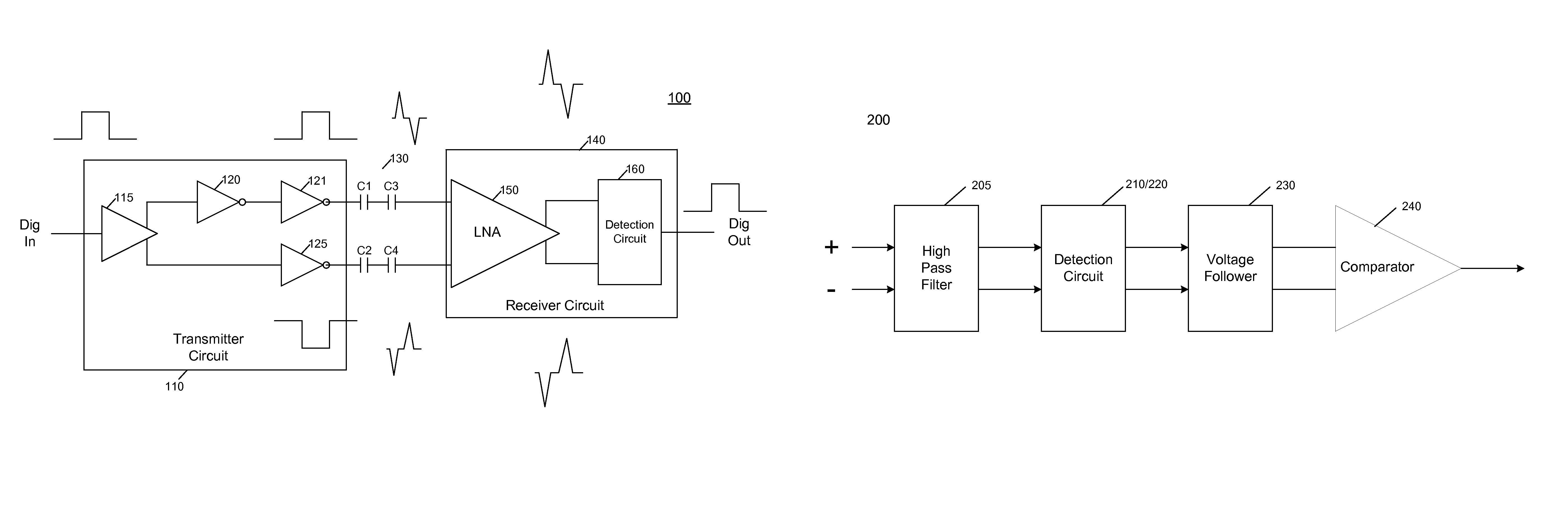
[0016]In various embodiments, isolation receiver circuitry can be implemented using a detection circuit to enable detection of digital signals communicated across the barrier with improved tolerance to noise and other interference. The detection circuit can be designed to be fast and sensitive in order to enable rapid detection of the input signals. Furthermore, a relatively constant gain of the detection circuit across a wide band of frequencies can be realized, improving performance.

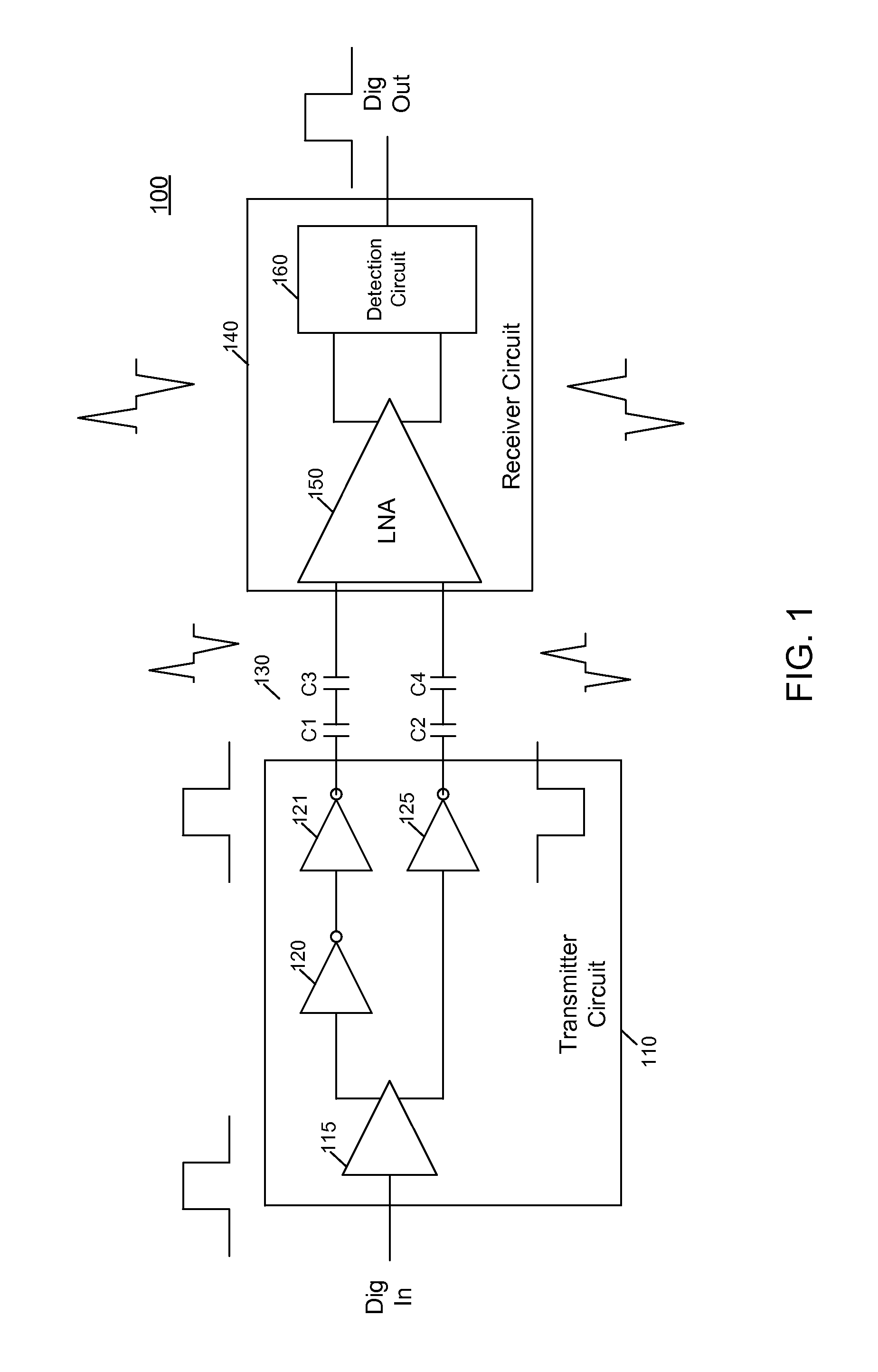
[0017]Referring now to FIG. 1, shown is a high level schematic diagram of isolation circuitry in accordance with an embodiment of the present invention. As shown in FIG. 1, circuit 100 can be an isolation circuit that may be implemented on one or more semiconductor die. In various embodiments, multiple die can be present and located within a single integrated circuit (IC) package as a multi-chip module (MCM), or the individual die can each be implemented in separate IC packages. Of course other embodim...


PUM


Abstract

One aspect of the present invention is directed to a circuit that includes an amplifier circuit disposed between an isolation link and a Schmitt trigger circuit to amplify a differential signal communicated over the isolation link and supply the amplified signal to the Schmitt trigger circuit. In turn, the Schmitt trigger circuit is coupled to the amplifier circuit to receive the differential signal and to supply a differential output signal corresponding to the differential signal communicated over the isolation link.

Description

BACKGROUND[0001]In many different systems, an isolation barrier can be provided to enable communication of signals across a given type of the isolation. Existing solutions for providing isolation links include the use of magnetic pulse couplers, magnetic resistive couplers, capacitive couplers and optical couplers. Other isolation functions include control of high voltage circuitry.[0002]Oftentimes isolation circuitry is used to communicate data and / or clock signals across the barrier to represent digital or analog values. Some systems implement an on-off keying (OOK) modulation scheme, where a modulated signal is transmitted. Sometimes communicating signals can be transmitted directly across the barrier. For example, with a capacitive isolation barrier, digital signals themselves can be transmitted across the barrier and transformed into pulses at a receiver input. However, attenuation due to the barrier makes it difficult to detect the received pulses correctly, especially in the ...

Claims


Application Information

Patent Timeline
IPC IPC(8): H04B1/38H04B1/18
CPCH04B3/50H04B3/30
Inventor DONG, ZHIWEILI, JINGDUFFY, MICHAEL L.MILLS, MICHAEL
Owner SKYWORKS SOLUTIONS INC
Why Eureka
Try Eureka