
Method and apparatus for producing bio-gas employing technology for improving quality of raw material fed thereto

a technology of raw material feed and production method, applied in the direction of filtration separation, multi-stage water/sewage treatment, separation process, etc., can solve the problems of increasing the capacity of the digestion reactor and/or equipment cost, reducing the productivity of bio-gas, etc., to achieve the effect of effective and efficient production of bio-gas

Inactive Publication Date: 2013-08-13
BOO KANG TECH CO LTD
View PDF9 Cites 0 Cited by
  • Summary
  • Abstract
  • Description
  • Claims
  • Application Information

AI Technical Summary

Benefits of technology

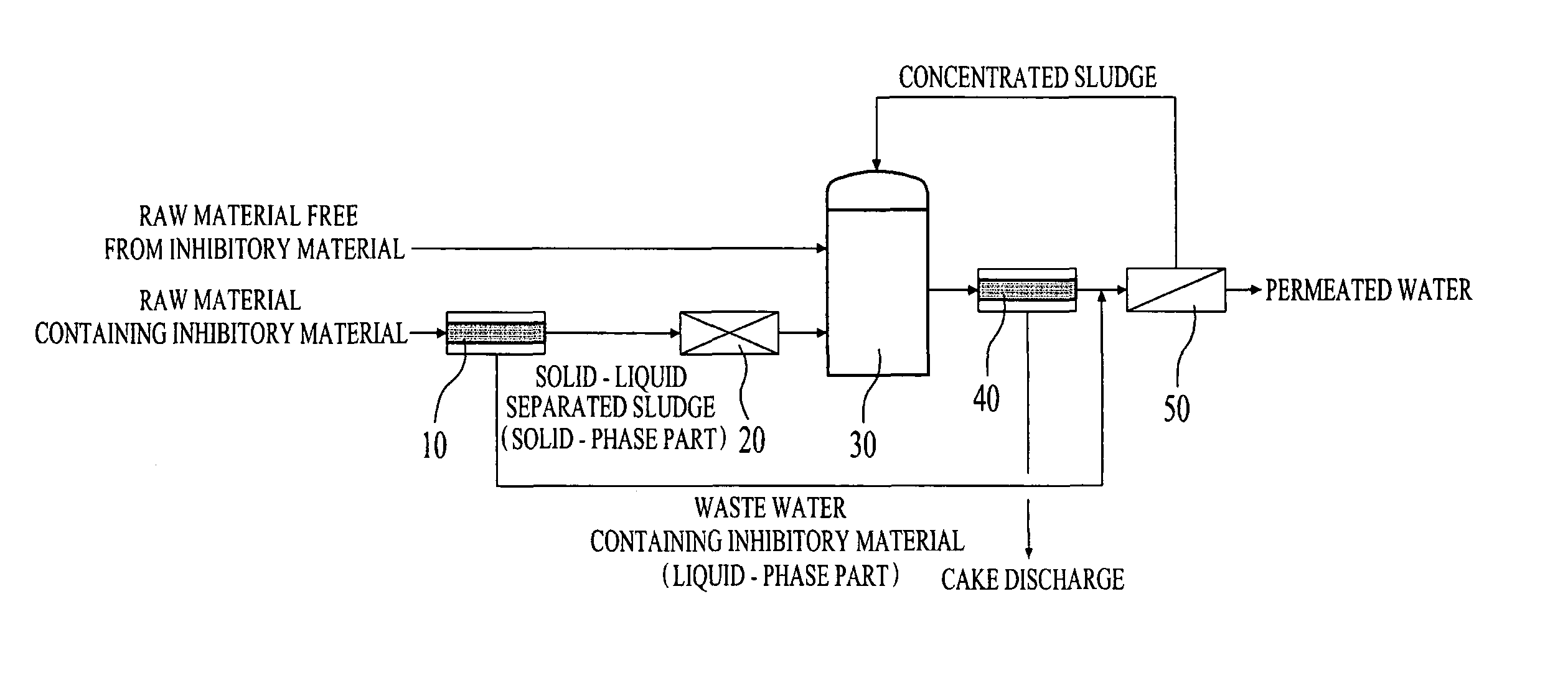
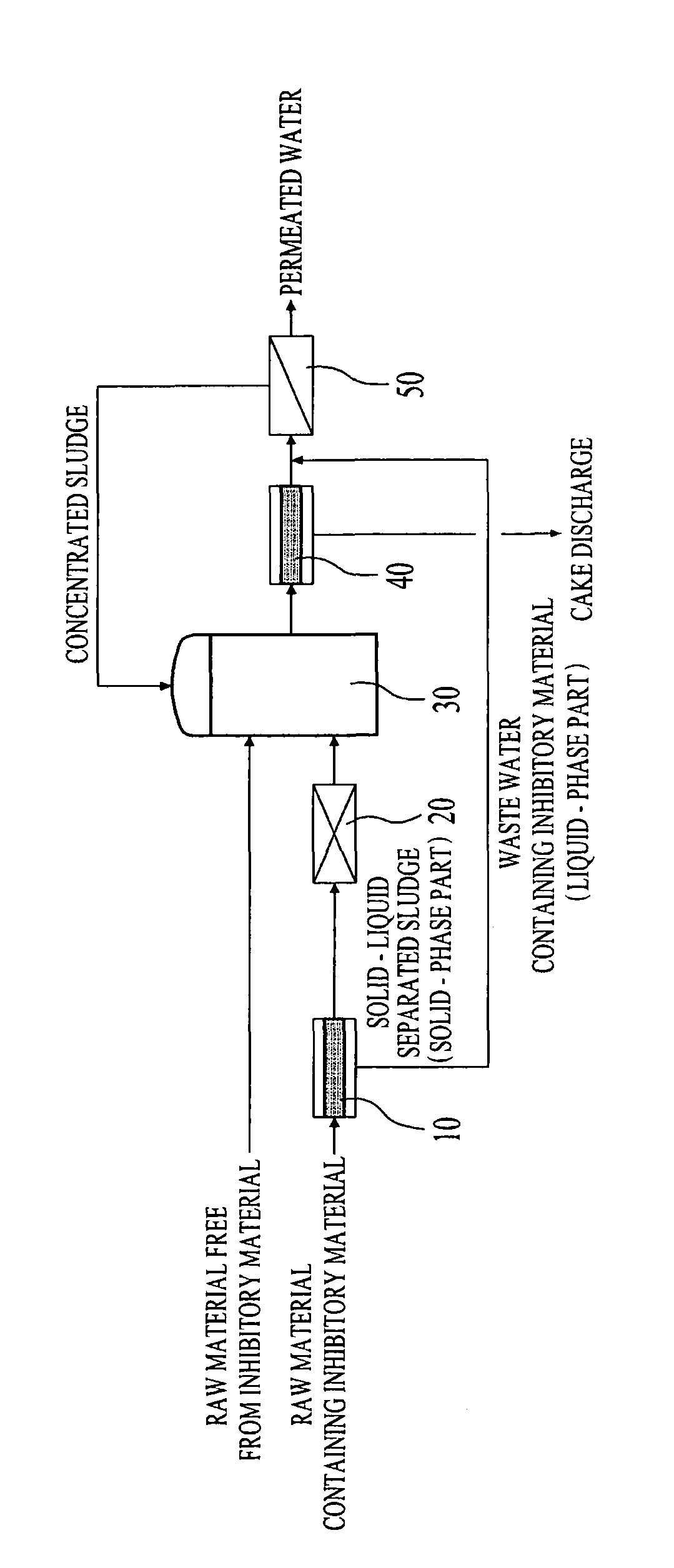
[0008]Therefore, in order to overcome the foregoing problems of conventional art, an object of the present invention is to provide a method and an apparatus for production of bio-gas, which includes introducing only a solid-phase sludge into an anaerobic digestion reactor, after removing inhibitory materials from a raw material to be fed thereto, through solid-liquid separation, to thereby appropriately maintain desired activity of microorganisms generating the bio-gas.
[0012]According to the present invention, before introducing a solid-phase sludge separated in the solid-liquid separator into the anaerobic digestion reactor, a solid-phase material contained in this sludge can be converted into a liquid-phase material by hydrolyzing the sludge (through high temperature, high pressure or ozone treatment, or the like). Dissolved matter (an organic material) converted into the liquid-phase material by hydrolysis, is then introduced into the anaerobic digestion reactor, in which the dissolved matter is degraded / ingested within a short time by anaerobic microorganisms to thereby enable effective and efficient production of bio-gas.
[0013]In addition, a treated solution (a leachate) containing a large amount of anaerobic microorganisms in the solid-liquid separator is introduced into a sludge concentrator (that is, a membrane separation device), followed by separation of the anaerobic microorganisms and concentration thereof to produce a concentrated sludge. Such a concentrated sludge is returned to the anaerobic digestion reactor or a raw material storage tank, thus maintaining a large amount of the anaerobic microorganisms in the anaerobic digestion reactor and enabling the microorganisms to exist therein for a long term.

Problems solved by technology

However, such main raw materials include a great amount of inhibitory materials (such as ammonia, sulfides, salt, heavy metals, etc.) that deteriorate activity of microorganisms used for producing bio-gas, depending on kinds of the organic waste.
When an organic waste (solid and / or liquid phase) is directly introduced into an anaerobic digestion reactor, inhibitory materials in the liquid-phase of the organic waste deteriorate activity of microorganisms and considerably decrease bio-gas productivity, in turn causing the digestion reactor to be shut-down.
In addition, since an organic waste in a solid-phase is fed into the anaerobic digestion reactor, it requires a long residence time in order to decompose the organic waste and causes problems such as increase in a capacity of the digestion reactor and / or equipment costs.
However, a typical anaerobic digestion reactor has a relatively small capacity and does not allow microorganisms to reside therein for a long term, thus not ensuring a desired amount of the microorganisms.
As a result, an amount of bio-gas to be generated may be decreased, in turn encountering malfunction or loss of function of the anaerobic digestion reactor.

Method used


Image

  • Method and apparatus for producing bio-gas employing technology for improving quality of raw material fed thereto
  • Method and apparatus for producing bio-gas employing technology for improving quality of raw material fed thereto

Examples


Embodiment Construction

[0016]Hereinafter, the present invention will be described in more detail, in conjunction with the accompanying drawing.

[0017]FIG. 1 schematically illustrates a structure of an apparatus for production of bio-gas according to the present invention. The apparatus for production of bio-gas according to the present invention has a configuration in that a first solid-liquid separator 10, a hydrolysis reactor 20, an anaerobic digestion reactor 30, a second solid-liquid separator 40 and a sludge concentrator 50 are sequentially arranged.

[0018]First, a raw material, for producing bio-gas is classified into one free from inhibitory materials and the other containing the inhibitory materials, wherein the former without the inhibitory material is directly introduced into the anaerobic digestion reactor 30 while the latter containing the inhibitory materials is fed to the same anaerobic digestion reactor 30 through the first solid-liquid separator 10 and the hydrolysis reactor 20.

[0019]The fir...


PUM

PropertyMeasurementUnit
temperatureaaaaaaaaaa
pressureaaaaaaaaaa
concentrationaaaaaaaaaa

Abstract

Disclosed are a method and an apparatus for production of bio-gas, capable of improving quality of a raw material to be fed thereto. Among the raw material, a part free from inhibitory materials is directly introduced an anaerobic digestion reactor while the other part containing the inhibitory materials is introduced into a first solid-liquid separator and separated into a solid-phase material free from the inhibitory materials and a liquid-phase material containing the inhibitory materials. The solid-phase material in the first solid-liquid separator is fed to the anaerobic digestion reactor after hydrolysis. A liquid waste in the anaerobic digestion reactor and a liquid-phase material in the first solid-liquid separator are concentrated by a sludge concentrator. Through solid-liquid separation of the raw material, only a solid-phase sludge removed from the inhibitory materials is fed to the anaerobic digestion reactor, thereby suitably maintaining desired activity of microorganisms used for producing bio-gas.

Description

RELATED APPLICATIONS[0001]This application claims priority from Korean Patent Application No. 10-2010-0053086, filed on Jun. 24, 2010 in the Korean Intellectual Property Office, the entire disclosure of which is incorporated herein by reference.BACKGROUND OF THE INVENTION[0002]1. Field of the Invention[0003]The present invention relates to a method and an apparatus for production of bio-gas employing a specific technology for improving quality of a raw material fed thereto.[0004]2. Description of the Related Art[0005]In production of bio-gas, organic waste and bio-mass are generally used as main raw materials. However, such main raw materials include a great amount of inhibitory materials (such as ammonia, sulfides, salt, heavy metals, etc.) that deteriorate activity of microorganisms used for producing bio-gas, depending on kinds of the organic waste. These inhibitory materials are mostly present as dissolved matters (in a liquid state) in water, while not existing in a solid porti...

Claims


Application Information

Patent Timeline
Patent Type & Authority Patents(United States)
IPC IPC(8): C02F3/28C02F11/04
CPCC02F3/2813C02F3/2853C12M21/04C12M45/04Y02E50/343C02F2101/10C02F2101/30C02F2103/20C02F2103/32Y02E50/30
Inventor EUM, YOUNG JINOH, GI YANGKIM, JANG GYUSUK, HUNYU, MYEONG JUNGLI, LONG
Owner BOO KANG TECH CO LTD
Learn More