
Cable tie

a cable tie and tie strap technology, applied in the field of cable tie straps, can solve the problems of limited cable tie strap length, large mold size, and many different-sized molds to be constructed, and achieve the effects of enhancing the connection strength

Active Publication Date: 2013-08-20
AVERY DENNISON CORP
View PDF38 Cites 22 Cited by
  • Summary
  • Abstract
  • Description
  • Claims
  • Application Information

AI Technical Summary

Benefits of technology

The present invention is related to a cable tie that is strong, inexpensive to manufacture, and has a simple design. The cable tie includes a strap with a front end, rear end, top surface, bottom surface, and side members. The strap has a connective segment at the front end, and a front portion is insert-molded onto the connective segment. The front portion has a head that forms a locked closed loop with the strap. The connective segment has a mechanical interlocking element to strengthen the connection between the strap and the front portion. This interlocking element can be a cutout or a hole in the strap or a protrusion on the front portion. The cable tie is suitable for various uses and provides a secure and reliable connection.

Problems solved by technology

As a primary drawback, the above-described process involves molding the entirety of a cable tie through a single injection molding step.
As a result, the length of the cable tie strap is limited by the size of its corresponding impression.
This typically results in the need for many differently-sized molds to be constructed.
As a secondary drawback, because the above-described process requires that the entirety of the cable tie be formed at one time, cable ties having long strap lengths (i.e., several feet) require correspondingly large molds.
Molds of such large size are particularly expensive to produce.
In addition, because cable tie molds typically have only a single gate through which molten plastic is injected, the cycle time can be rather long as the molten plastic must travel through the single gate in the mold until it fills the entireties of all of the impressions.
In addition, the aforementioned forcing of the molten plastic through the entireties of the impressions often results in some degradation of the molten plastic material, such degradation being undesirable.
Even though a metal rivet adequately retains the head and strap portions of a two-piece cable tie together, it has been found that the cost associated with both the metal material requirement and the complex mechanical driving process renders the rivet connection method unfavorable for mass production.

Method used


Image

  • Cable tie
  • Cable tie
  • Cable tie

Examples


Embodiment Construction

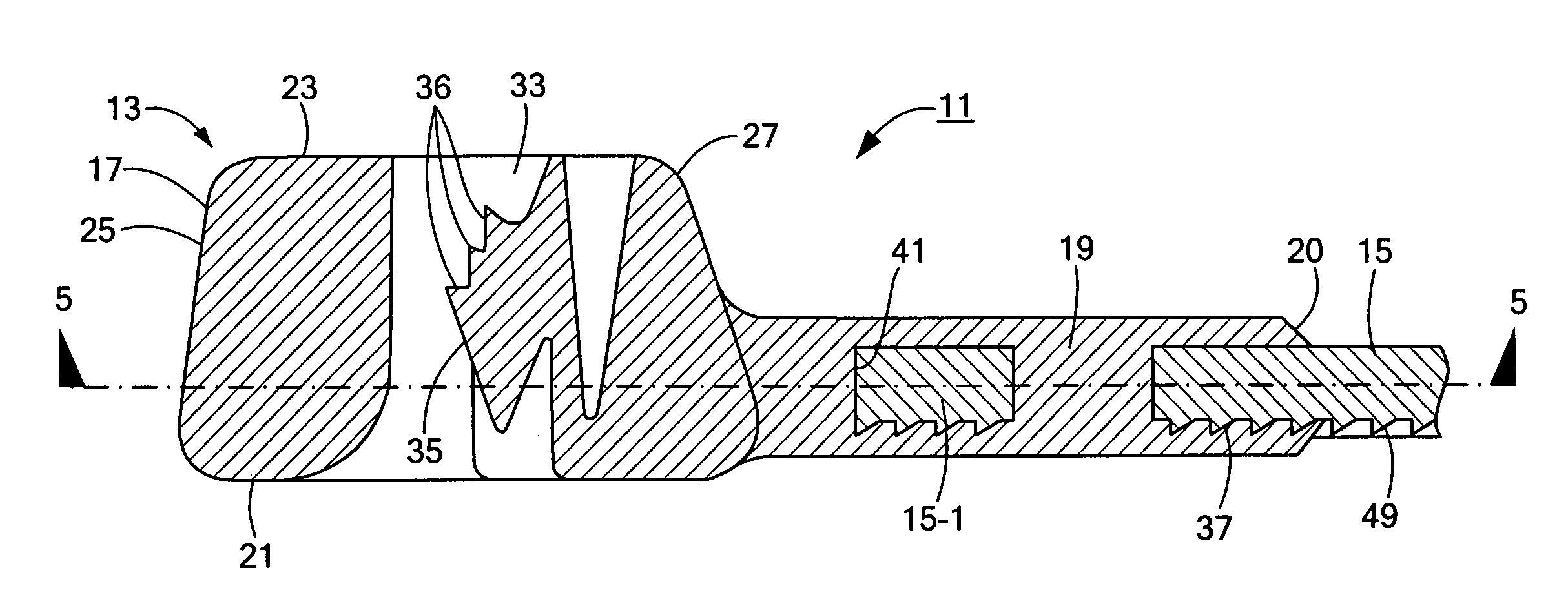
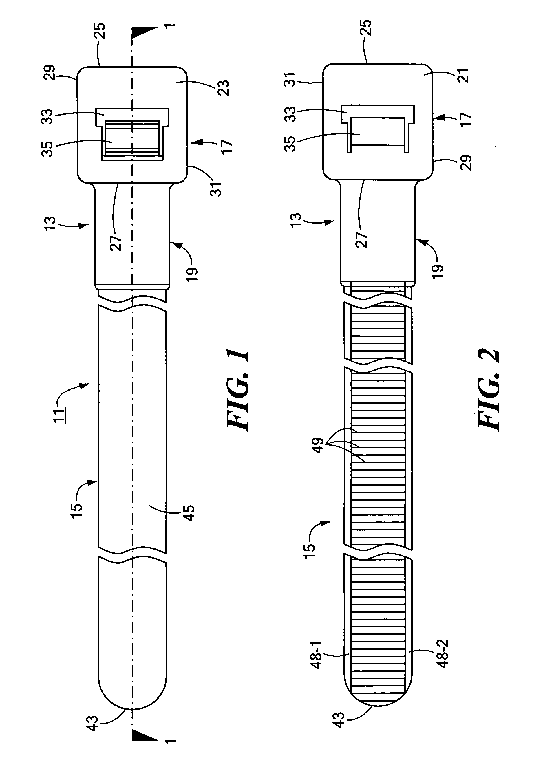
[0060]Referring now to FIGS. 1 and 2, there are shown various views of a cable tie constructed according to the teachings of the present invention, the cable tie being represented generally by reference numeral 11. In use, cable tie 11 can be formed into a locked closed loop in order to bundle together a plurality of objects, such as cables and / or wires.

[0061]The present inventors have determined that the failure of two-piece cable ties of the type described in the '855 patent most commonly occurs as a result of either pawl failure or insert-mold failure rather than strap failure. Accordingly, as will be described in greater detail below, cable tie 11 combines the basic design and method of manufacture of the two-piece cable disclosed in the '855 patent with certain design and manufacturing enhancements that result in an increased load rating, these enhancements serving as the primary novel features of the present invention. More specifically, the enhancements of the present inventi...


PUM


Abstract

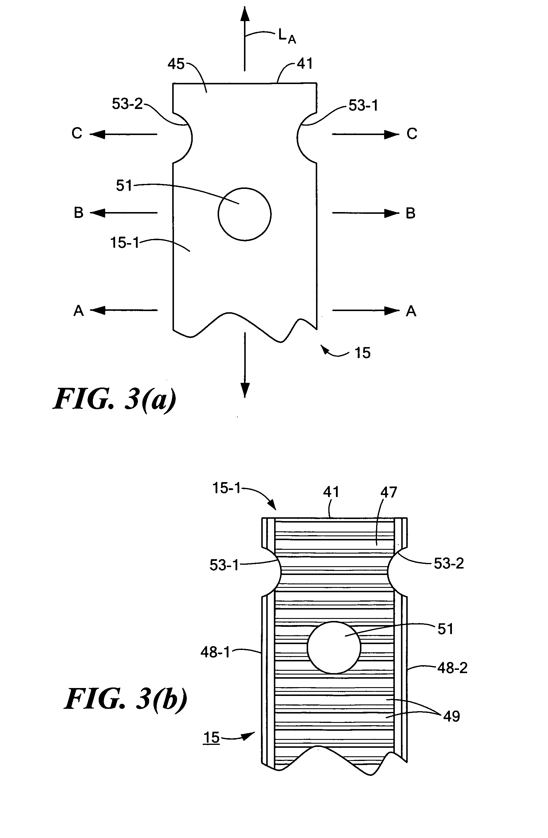
A two-piece cable tie for bundling a plurality of objects, such as cables or wires, includes a front portion that is insert-molded onto a connective segment of a flexible strap, the front portion being constructed out of a higher tensile strength plastic than the strap to maximize the load rating of the tie without significantly increasing material costs. In one embodiment, the connective segment of the strap is shaped to include a pair of opposing semi-circular cutouts in its side rails to enhance the strength of mechanical bonding achieved by the front portion around the strap. In addition, the connective segment is shaped to include a circular hole that is offset longitudinally from the opposing cutouts, the diameter of the circular opening not exceeding 40% of the maximum width of the strap to ensure the integrity and strength of the strap along the entirety of its length.

Description

CROSS-REFERENCE TO RELATED APPLICATIONS[0001]The present application claims the benefit under 35 U.S.C. 119(e) of U.S. provisional Patent Application Ser. No. 61 / 208,336, filed Feb. 23, 2009, the disclosure of which is incorporated herein by reference.BACKGROUND OF THE INVENTION[0002]The present invention relates generally to cable ties and relates more particularly to cables ties formed from two separately molded plastic components.[0003]Cable ties, also known as bundling ties and harnessing devices, are well known devices commonly used in the art to couple together a plurality of elongated objects, such as wires or cables. One type of cable tie which is well known and widely used in the art comprises an elongated strap having an apertured head disposed at one end thereof. The opposite end of the elongated strap is typically shaped to define a tail of narrowed width adapted for insertion through the apertured head to form a closed loop. A plurality of serrations or teeth are formed...

Claims


Application Information

Patent Timeline
Patent Type & Authority Patents(United States)
IPC IPC(8): B65D63/10
CPCB65D63/1072Y10T24/1498B65D63/10F16B2/08H02G1/06
Inventor SHILALE, THOMASBUROUT, III, CHARLES J.SCHUTTLER, DAVID L.
Owner AVERY DENNISON CORP
Learn More