Brain cooling apparatus and fluid injection apparatus used therefor

a technology for brains and apparatuses, applied in the field of brain cooling apparatuses, can solve the problems of brain sequela, ischemic neuronal damage, and short oxygen supply, and achieve the effects of reducing the risk of brain damage, and reducing the effect of oxygen consumption

Inactive Publication Date: 2013-09-03
UNIV OKAYAMA
View PDF16 Cites 5 Cited by
  • Summary
  • Abstract
  • Description
  • Claims
  • Application Information

AI Technical Summary

Benefits of technology

[0012]According to the present invention, a fluid is injected into the storage portion, with the tube-shaped member kept inserted in the living body. This allows the storage portion to adhere closely to the pharyngeal part. Thus, the pharyngeal part can be cooled by the cooled fluid inside of the storage portion. At and near the pharyngeal part, there are numerous blood vessels which supply blood to the brain. Therefore, the storage portion cools these blood vessels, thereby cooling the blood in the blood vessels and cooling the brain.
[0013]Hence, according to the present invention, the blood vessels which lie relatively close to the brain is cooled from the inside of the body (i.e., the pharyngeal part). This allows the brain to cool within a short period of time. In addition, the brain is cooled via blood, and thus, it can be cooled adequately up to its sub-cortical tissue.
[0015]Furthermore, according to the present invention, using the tube-shaped member, an airway is maintained in the respiratory tract of the living body. This makes it possible to simultaneously conduct a cardiac-arrest resuscitation treatment such as artificial respiration, and a hypothermic therapy.

Problems solved by technology

This shortage of oxygen may kill brain cells.
In other words, it is known that it may cause so-called ischemic neuronal damage.
However, even if this treatment resuscitates the living body from the cardiac-arrest state, the above described ischemic neuronal damage may give a sequela to the brain.
Thus, it takes time to lower the brain temperature, and in addition, it is difficult to cool the brain adequately up to its sub-cortical tissue.
Besides, if a living body is resuscitated from the cardiac-arrest state with the whole body cooled using the blanket, the temperature of the whole body may lower, thereby inducing arrhythmia.

Method used


Image

  • Brain cooling apparatus and fluid injection apparatus used therefor
  • Brain cooling apparatus and fluid injection apparatus used therefor
  • Brain cooling apparatus and fluid injection apparatus used therefor

Examples


Embodiment Construction

[0027]Hereinafter, preferred embodiments of the present invention will be described with reference to the drawings.

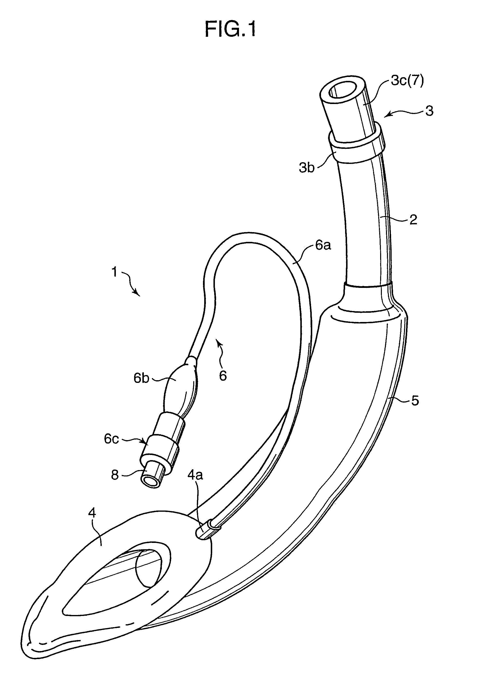
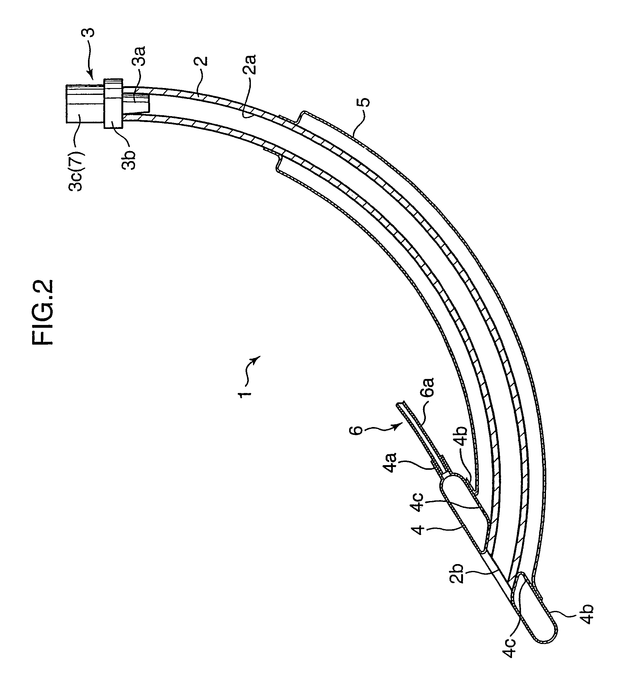
[0028]FIG. 1 is a perspective view of a laryngeal mask 1 according to an embodiment of the present invention, showing its whole configuration. FIG. 2 is a side sectional view of the laryngeal mask 1 in FIG. 1. FIG. 3 is a schematic enlarged sectional partial view of the front-end part of the laryngeal mask 1 in FIG. 2.

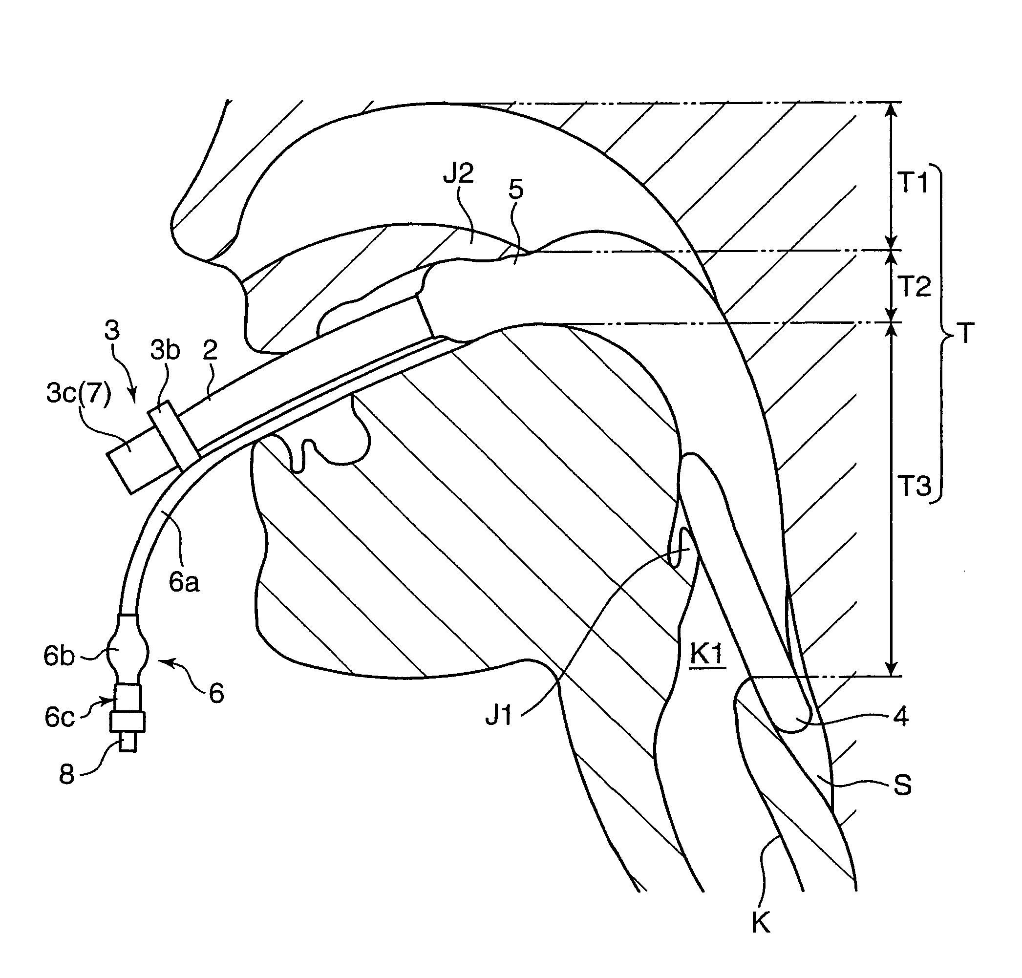
[0029]With reference to each figure, the laryngeal mask 1 includes: a tube body 2 which has a substantially arc shape; a connector 3 which is attached to the basic-end part of this tube body 2; a cuff 4 which is placed on an outer surface of the front-end part of the tube body 2; a pharyngeal cuff (or a storage portion) 5 which is the tube body 2 so the it extends from the cuff 4 toward the side of the basic-end part; and an injection and discharge portion 6 which can inject and discharge a fluid into and from both cuffs 4, 5.

[0030]The tube body 2 is made ...


PUM


Abstract

A brain cooling apparatus includes a tube body 2 which can maintain an airway in the respiratory tract of a living body; a pharyngeal cuff 5 which is provided in the peripheral part of this tube body 2 and can store a cooled fluid; and an injection and discharge portion 6 which can inject and discharge a fluid into and from this pharyngeal cuff 5, in which the pharyngeal cuff 5 is flexible enough to inflate and deflate when a fluid is injected and discharged, and when a fluid is injected in a state where an airway in the respiratory tract of a living body is maintained by the tube body 2, the inflated pharyngeal cuff adheres closely to the pharyngeal part T of the living body.

Description

TECHNICAL FIELD[0001]The present invention relates to a brain cooling apparatus.BACKGROUND ART[0002]In a living body such as the human body, when a respiratory function or a circulatory function becomes insufficient, such as cardiac arrest (hereinafter, referred to as a cardiac-arrest state), oxygen which is supplied to a brain falls short. This shortage of oxygen may kill brain cells. In other words, it is known that it may cause so-called ischemic neuronal damage.[0003]Hence, with respect to a living body in the cardiac-arrest state, a treatment such as artificial respiration is given for resuscitating the living body from the cardiac-arrest state. However, even if this treatment resuscitates the living body from the cardiac-arrest state, the above described ischemic neuronal damage may give a sequela to the brain.[0004]In view of such circumstances, in recent years, hypothermic therapy is proposed as a treatment for preventing ischemic neuronal damage from being caused. In such t...

Claims


Application Information

Patent Timeline
Patent Type & Authority Patents(United States)
IPC IPC(8): A61H3/04A61F7/00A61F7/02A61F7/12A61M16/04
CPCA61F7/12A61M16/04A61M16/0409A61M16/0438A61F2007/0002A61F2007/0056A61M16/0461
Inventor TAKEDA, YOSHIMASAMORITA, KIYOSHI
Owner UNIV OKAYAMA
Why Eureka
Try Eureka