Noncontact scanning system

a scanning system and non-contact technology, applied in the field of scanning devices and systems, can solve the problems of increasing the time, complexity and expense of scanning process, repositioning objects, and measurement of size in multiple directions that would require multiple reorientations of objects, and achieves the effect of convenient triangulation and high degree of precision

Active Publication Date: 2013-09-03
CYBEROPTICS
View PDF28 Cites 9 Cited by
  • Summary
  • Abstract
  • Description
  • Claims
  • Application Information

AI Technical Summary

Benefits of technology

[0031]Alternatively, the radiant energy can be directed to the object as a volume, e.g. defining a cone, forming a defined surface area corresponding to the surface segment, in which case the object is held stationary during the scan. In either approach, it is advantageous to provide radiant energy sources and radiant energy sensors in pairs, spaced with respect to one another and fixed in a scanning device. This approach facilitates the use of triangulation to generate the surface data sets.
[0032]The scanning sequence preferably comprises directing the radiant energy onto adjacent selected segments that overlap one another. This results in surface data sets for adjacent segments with redundant data corr

Problems solved by technology

Nonetheless, most scanning systems require multiple orientations of the scanned object to provide a complete, uninterrupted scan of the entire exterior surface.
At the very least, an object supported on a horizontal table or base must be turned over to provide scanner access to its previously inaccessible “underside.” Frequently, the shape of an object does not lend itself to a simple “turning over” to reveal previously unexposed surface regions, requiring several manual or robotic reorientations of the object between successive scans.
The need to reposition the object increases the time, complexity and expense of the scanning process, not only due to the additional scans and repositioning between scans, but also due to the difficulty encountered in registering the separate scans, i.e. properly aligning the scans with respect to each othe

Method used


Image

  • Noncontact scanning system
  • Noncontact scanning system
  • Noncontact scanning system

Examples


Embodiment Construction

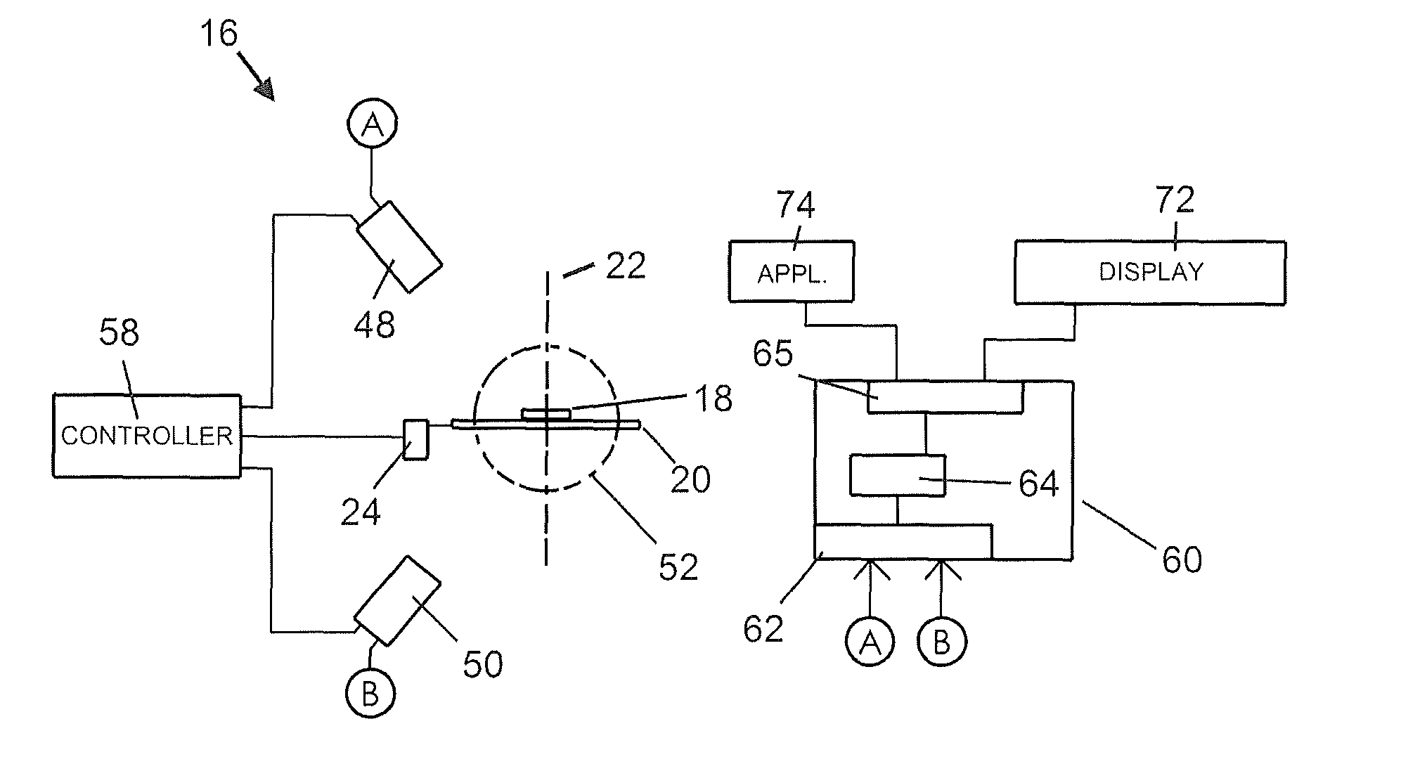
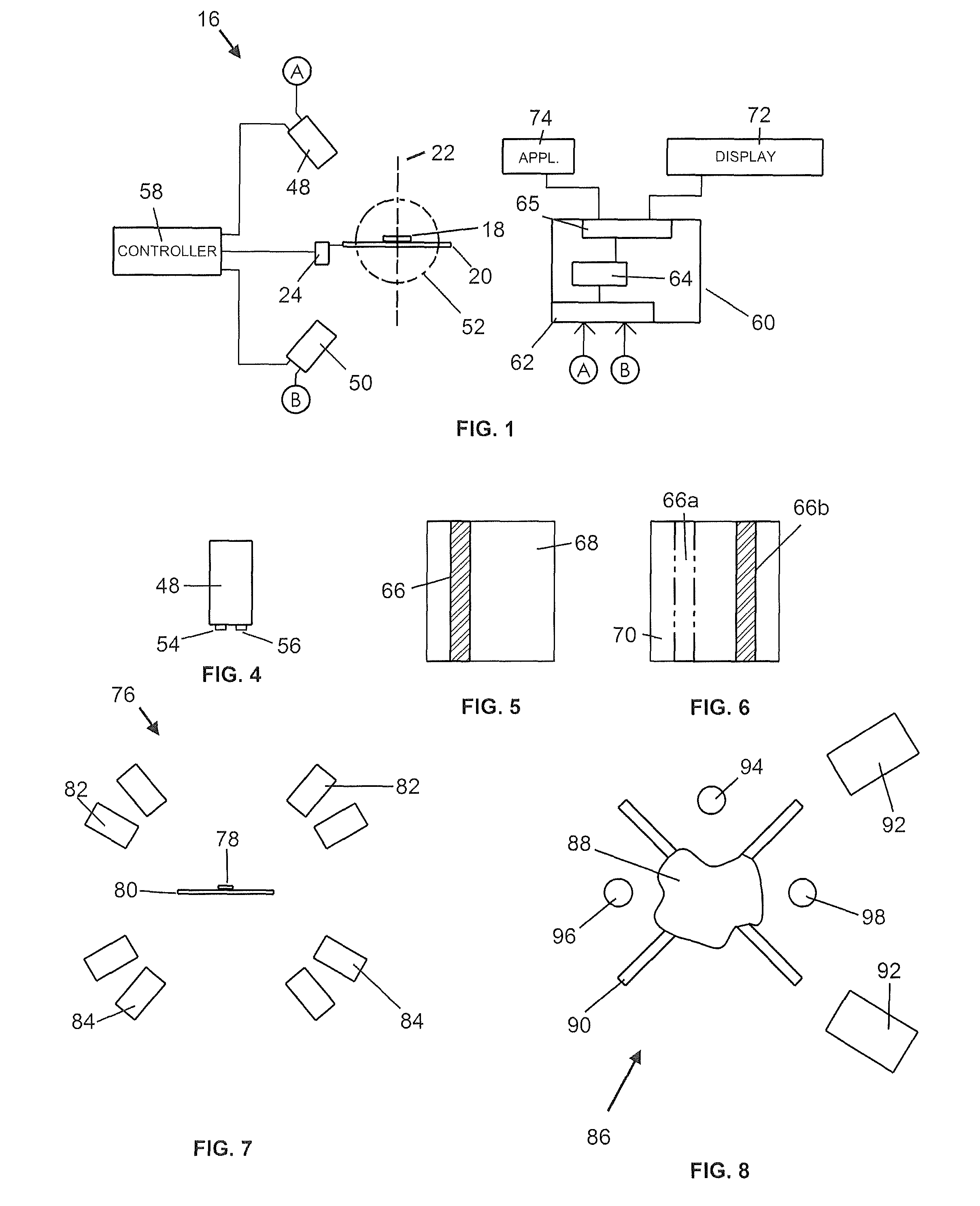
[0042]Turning now to the drawings, FIG. 1 illustrates an object scanning system 16 configured to perform a complete exterior surface scan of an object, and to use data generated by the scanning sequence to generate a three dimensional representation of an entire continuous exterior shape of the object. An object 18 to be scanned is supported for controlled motion on a table or base 20 having a horizontal upper surface and rotatable about a vertical axis 22 with respect to a fixed support frame. A motor 24 is operatively coupled to table 20 to controllably rotate the table and object 18, at a constant speed or in a sequence of steps for indexing the position of the object, as required.

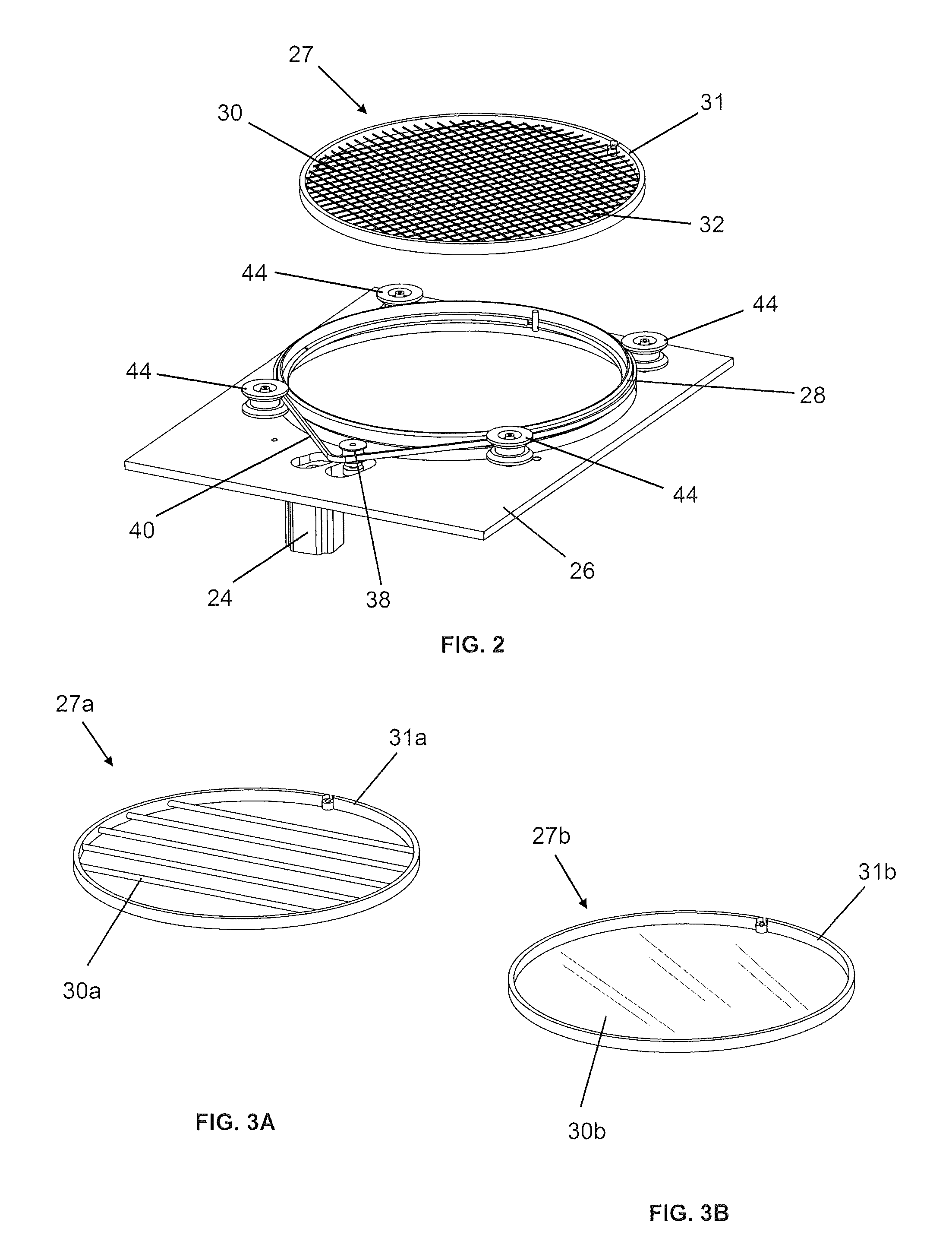
[0043]FIG. 2 shows the object support structure in more detail. Table 20 includes a stationary frame or platform 26 and a circular rim 28 mounted to rotate relative to the platform. An insert 27 includes a circular rim 31 and multiple carbon fiber rods 30 extended in two perpendicular directions to form...


PUM


Abstract

A noncontact object scanning system includes a horizontal table rotatable on a vertical axis, one or more scanners above the table and one or more scanners below the table. The table allows passage of radiant energy therethrough due to its transparency or construction as a nonreflective grid. A controller automatically steps the scanners through a scanning sequence, each scan associated with a segment of the object's exterior surface. Surface segments scanned from above the table and from below the table combine to provide a comprehensive scan of the entire exterior surface. Adjacent surface segments overlap one another to provide redundant data used to overcome shadowing effects from the grid and to accurately align and merge the segments into a three dimensional representation of the complete exterior shape of the object. The scanners can incorporate color responsive light detectors whereby the three dimensional representation portrays color and shape.

Description

BACKGROUND OF THE INVENTION[0001]The present invention relates to scanning devices and systems for generating three dimensional data characterizing the exterior or surface of a scanned object, and more particularly to noncontact scanning devices and systems automated to minimize the need for operator intervention.[0002]The ability to replicate the exterior surface of an article, accurately in three dimensional space, is becoming increasingly useful in a wide variety of fields. Industrial and commercial applications include reverse engineering, inspection of parts and quality control, and for providing digital data suitable for further processing in applications such as computer aided design and automated manufacturing. Educational and cultural applications include the reproduction of three dimensional works of art, museum artifacts and historical objects, facilitating a detailed study of valuable and often fragile objects, without the need to physically handle the object. Medical ap...

Claims


Application Information

Patent Timeline
IPC IPC(8): G01B11/30
CPCG01B11/245G01B2210/44
Inventor SCHUSTER, C. MARTINHETZLER, GREGORY G.
Owner CYBEROPTICS
Why Eureka
Try Eureka