Compound X-ray lens having multiple aligned zone plates

Active Publication Date: 2013-09-03
CARL ZEISS X RAY MICROSCOPY
View PDF13 Cites 37 Cited by
  • Summary
  • Abstract
  • Description
  • Claims
  • Application Information

AI Technical Summary

Benefits of technology

[0012]This invention pertains to methods to fabricate compound x-ray lenses including two or more zone plate lenses. In these compound lenses, the individual zone plates are placed in proximity along the longitudinal d

Problems solved by technology

Therefore, the challenge of making high resolution and high efficiency zone plate lenses becomes the challenge of making structures with high thickness-to-width aspect ratio, especially with increasing x-ray energy.
Such a high aspect ratio often poses significant difficulty for fabricating a single optic element.
Fabricating these zones challenges existing

Method used


Image

  • Compound X-ray lens having multiple aligned zone plates
  • Compound X-ray lens having multiple aligned zone plates
  • Compound X-ray lens having multiple aligned zone plates

Examples


Example

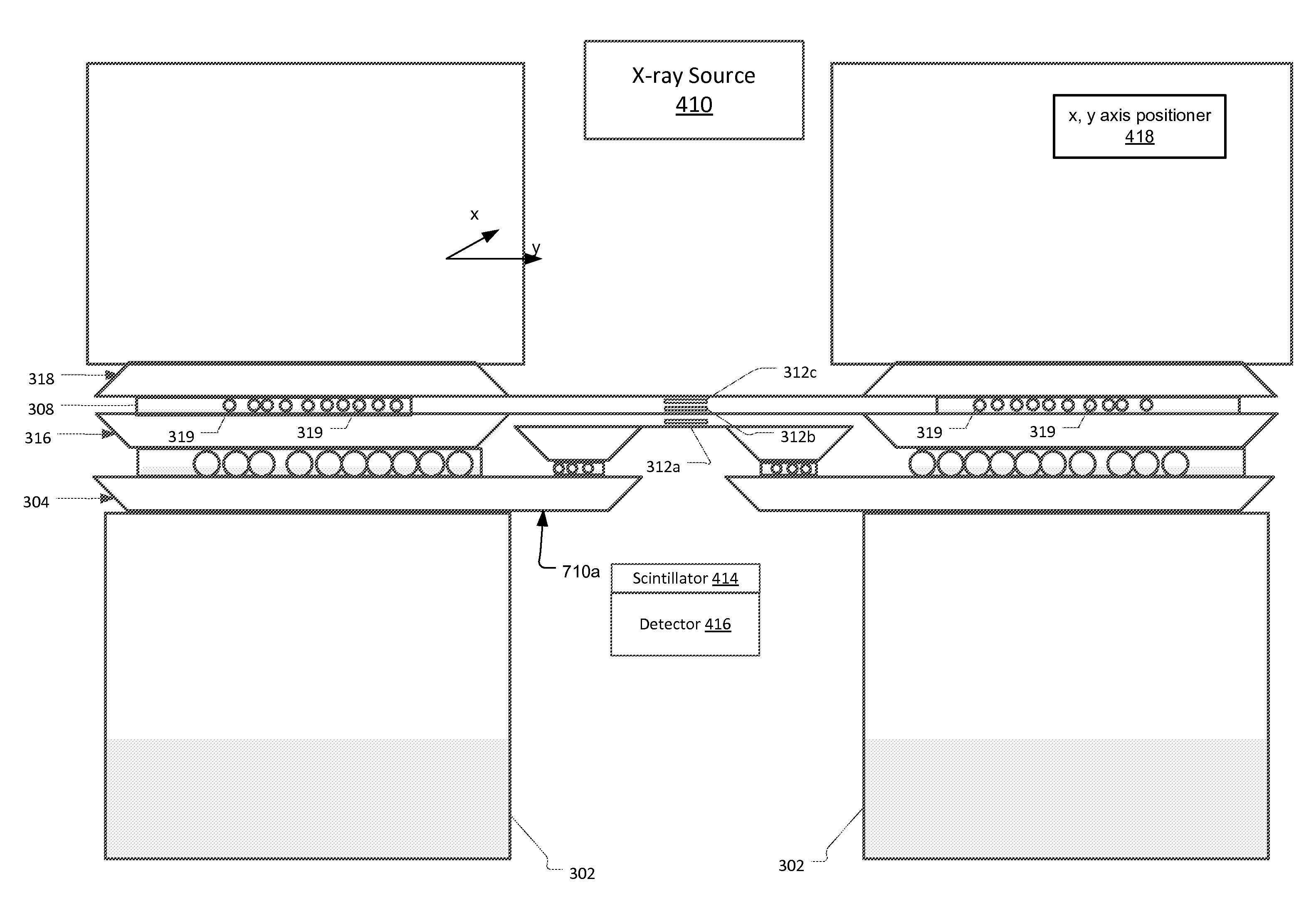
[0034]FIG. 4 shows an x-ray imaging system that has been constructed according to the principles of the present invention.

[0035]The system has an x-ray source 110 that generates an x-ray beam 112 along the optical axis 122. In the current embodiment, the source is a beamline of a synchrotron x-ray generation facility. In other embodiments, lower power sources are used, such as laboratory sources. Such sources often generate x-rays by bombarding a solid target anode with energetic electrons. Specific examples include microfocus x-ray sources and rotating anode sources.

[0036]The x-ray beam 112 is preferably a hard x-ray beam. In one embodiment, its energy is about 10 keV. Generally, the beam's energy is between about 2 keV and 25 keV. These higher energies ensure good penetration through any intervening coating, e.g. fluid layer, on the sample 10.

[0037]The condenser 114 collects and focuses the x-ray beam 112 from the source 110. For the full field imaging setup, a suitable illuminati...


PUM


Abstract

A compound zone plate comprising a first zone plate frame including a first zone plate, a second zone plate frame including a second zone plate, and a base frame to which the first zone plate frame and the second zone plate frame are bonded. In examples, two more zone plates are added to make a four element optic. In the assembly process, the microbeads are used to ensure the parallelism, dial in the distance precisely between the zone plates by selecting the microbead size, possibly in response to the width of the frames, and ensure low friction lateral movement enabling nanometer precision alignment of the zone plates with respect to each other prior to being fixed by the adhesive. That is, when the frames are pressed together to ensure parallelism, it is still possible to align them to each other since the microbead layer facilitates the inplane movement of the alignment process.

Description

RELATED APPLICATIONS[0001]This application claims the benefit under 35 USC 119(e) of U.S. Provisional Application No. 61 / 233,375, filed on Aug. 12, 2009, which is incorporated herein by reference in its entirety.BACKGROUND OF THE INVENTION[0002]Lens-based high-resolution x-ray microscopy largely resulted from research work at synchrotron radiation facilities in Germany and United States starting in the 1980's. While projection-type x-ray imaging systems with up to micrometer resolution have been widely used since the discovery of x-ray radiation, ones using x-ray lens with sub-100 nanometer (nm) resolution began to enter the market only this century. These high-resolution microscopes are configured similarly to visible-light microscopes with an optical train typically including an x-ray source, condenser, objective lens, and detector.[0003]Because x rays do not refract significantly in most materials, nearly all such x-ray microscopes use diffractive objective lenses, called Fresnel...

Claims


Application Information

Patent Timeline
IPC IPC(8): G21K1/00
CPCG21K1/06G01N23/04G21K7/00G21K1/067G01N23/041
Inventor LYON, ALAN FRANCISFESER, MICHAELYUN, WENBINGCHEN, SHARON
Owner CARL ZEISS X RAY MICROSCOPY
Why Eureka
Try Eureka