Diagnostic test pattern generation for small delay defect

a technology of diagnostic test pattern and delay defect, which is applied in the direction of testing circuit, resistance/reactance/impedence, instruments, etc., can solve the problem that the majority of devices that fail due to delay defects fail, and the distribution of delay-related failures is skewed toward small delays. the effect of small delay defects

Active Publication Date: 2013-09-03
SIEMENS PROD LIFECYCLE MANAGEMENT SOFTWARE INC
View PDF4 Cites 5 Cited by
  • Summary
  • Abstract
  • Description
  • Claims
  • Application Information

AI Technical Summary

Problems solved by technology

Experimental data going back two decades have shown the distribution of delay-related failures is skewed toward small delays.
That is, the majority of devices that fail due to delay defects fail because of “small delay defects.” Small delay defects contribute to delays shorter than the clock cycles associated with the design and process technology node.
As design sizes and performance continue to increase, more and more designs will be susceptible to small delay defects.
Detecting and isolating small delay defects, therefore, have attracted considerable effort in the VLSI (very-large-scale integration) test community.
Consequently, some small delay defects may not be detected when the paths activated are too short for any delay effects to be observed at a scan cell.
Unfortunately, the number of paths as a function of circuit size can grow exponentially, and it is therefore only practical to target a limited number of critical paths with this fault model.
Even after small delay defects are detected, isolating and identifying these defects remain challenging.
As such, each failure captured may be associated with a large number of defect suspects, leading to low diagnosis resolutions.
While timing information from a logical or physical design may be used to improve diagnosis resolutions, the timing information is often insufficient as many small delay defects are caused by manufacturing process variations.
Thus, it is more difficult to pinpoint and locate small delay defects.
While both approaches work well, the diagnosis resolution sometimes is limited by production test patterns or the number of failures collected on a tester.
Neither method, however, is designed to target small delay defects.
Accordingly, some small delay defects may be missed when none of the long paths required for detecting these small delay defects are activated by the test pattern set generated.
As already mentioned, the timing information and static timing analysis might be insufficient for diagnosing small delay defects due to timing model inaccuracy and manufacturing process variations.

Method used


Image

  • Diagnostic test pattern generation for small delay defect
  • Diagnostic test pattern generation for small delay defect
  • Diagnostic test pattern generation for small delay defect

Examples


Embodiment Construction

[0017]Various aspects of the present invention relate to DTPG techniques for small delay defects. In the following description, numerous details are set forth for the purpose of explanation. However, one of ordinary skill in the art will realize that the invention may be practiced without the use of these specific details. In other instances, well-known features have not been described in details to avoid obscuring the present invention.

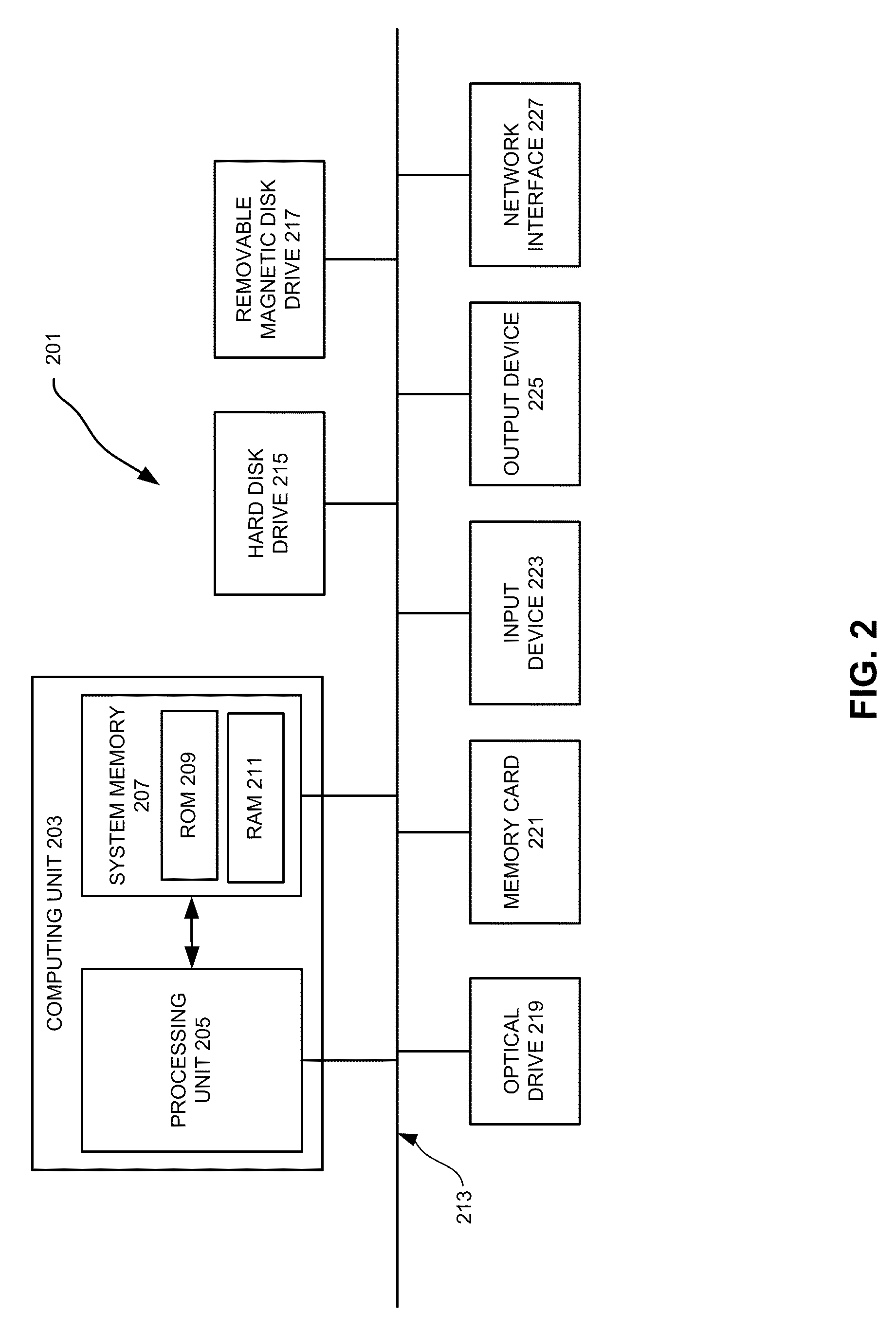
[0018]Some of the techniques described herein can be implemented in software instructions stored on a computer-readable medium, software instructions executed on a computer, or some combination of both. Some of the disclosed techniques, for example, can be implemented as part of an electronic design automation (EDA) tool. Such methods can be executed on a single computer or a networked computer.

[0019]Although the operations of the disclosed methods are described in a particular sequential order for convenient presentation, it should be understood tha...


PUM


Abstract

Methods of diagnostic test pattern generation for small delay defects are based on identification and activation of long paths passing through diagnosis suspects. The long paths are determined according to some criteria such as path delay values calculated with SDF (Standard Delay Format) timing information and the number of logic gates on a path. In some embodiments of the invention, the long paths are the longest paths passing through a diagnosis suspect and reaching a corresponding failing observation point selected from the failure log, and N longest paths are identified for each of such pairs.

Description

RELATED APPLICATIONS[0001]This application claims priority to U.S. Provisional Patent Application No. 61 / 172,881, entitled “Diagnostic Test Generation For Small Delay Defect,” filed on Apr. 27, 2009, and naming Ruifeng Guo et al. as inventors, which application is incorporated entirely herein by reference.FIELD OF THE INVENTION[0002]The present invention is directed to generating test patterns for fault diagnosis of integrated circuits. Various aspects of the invention may be particularly useful for improving the diagnosis resolution for small delay defect.BACKGROUND OF THE INVENTION[0003]Experimental data going back two decades have shown the distribution of delay-related failures is skewed toward small delays. That is, the majority of devices that fail due to delay defects fail because of “small delay defects.” Small delay defects contribute to delays shorter than the clock cycles associated with the design and process technology node. As design sizes and performance continue to i...

Claims


Application Information

Patent Timeline
Patent Type & Authority Patents(United States)
IPC IPC(8): G01R31/00
CPCG01R31/318328
Inventor GUO, RUIFENGCHENG, WU-TUNGKOBAYASHI, TAKEOTSAI, KUN-HAN
Owner SIEMENS PROD LIFECYCLE MANAGEMENT SOFTWARE INC
Why Eureka
Try Eureka