
Method of installing a foundation system for modular system-smart buildings

a modular system and foundation system technology, applied in the field of installing foundation systems, can solve the problems of adding additional costs and time, requiring a lot of site preparation, etc., and achieve the effect of simple and convenient assembly

Active Publication Date: 2013-09-10
MILLER MARTIN P
View PDF18 Cites 13 Cited by
  • Summary
  • Abstract
  • Description
  • Claims
  • Application Information

AI Technical Summary

Benefits of technology

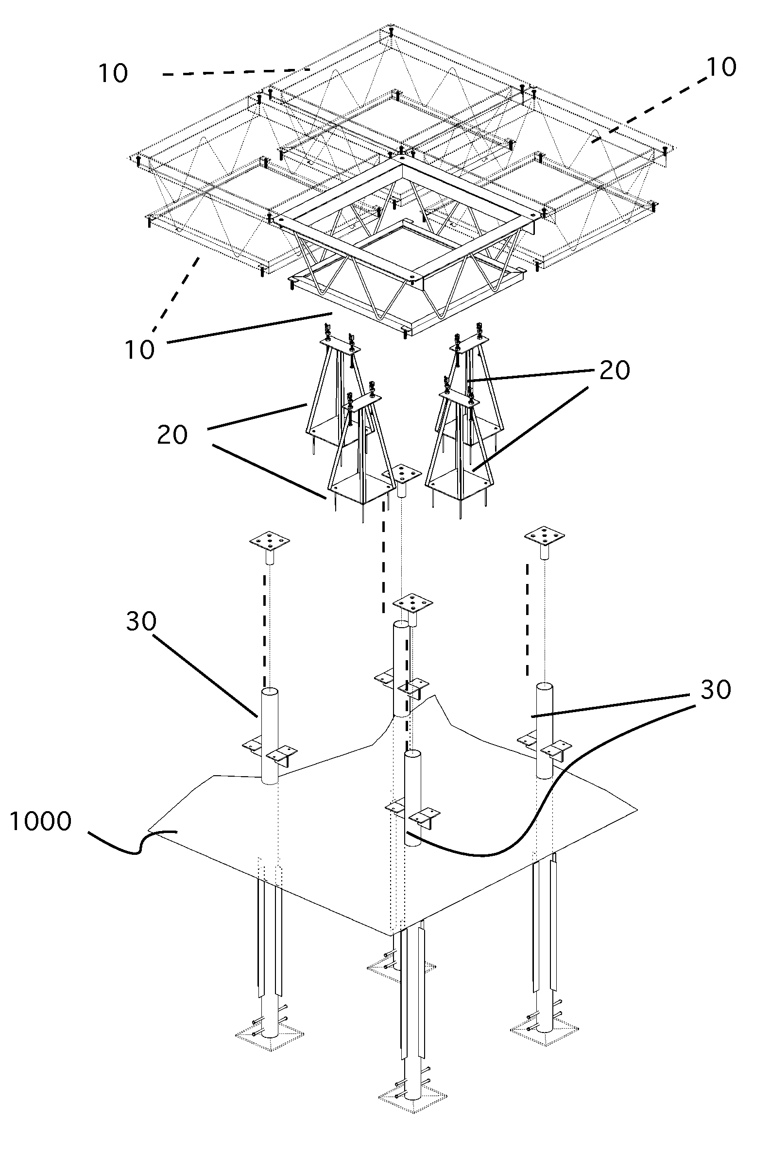
The invention is a new type of foundation system that solves problems with conventional concrete foundations. It consists of a modular structure that requires no heavy equipment, can be assembled quickly, and can be easily disassembled for emergency housing or permanent construction. It allows for easy addition of parts of the building and can also be removed if desired. This foundation system is hurricane and tornado proof, and uses box bar joists and square units that are assembled based on a grid layout. No forms or complex structures are needed for installation. The unique leveling system ensures the foundation is complete and ready for building. Overall, this invention provides a faster, easier, and more flexible solution for building foundations.

Problems solved by technology

Although these walls have been proven to be strong and reliable, they require quite a lot of site preparation, including surveying, grading, excavating, rebar install, setting concrete forms, pouring concrete (or building wall of block), and then back filling around the foundation.
Additionally, in many areas, the foundation wall is waterproofed, which adds additional costs and time.

Method used


Image

  • Method of installing a foundation system for modular system-smart buildings
  • Method of installing a foundation system for modular system-smart buildings
  • Method of installing a foundation system for modular system-smart buildings

Examples


Embodiment Construction

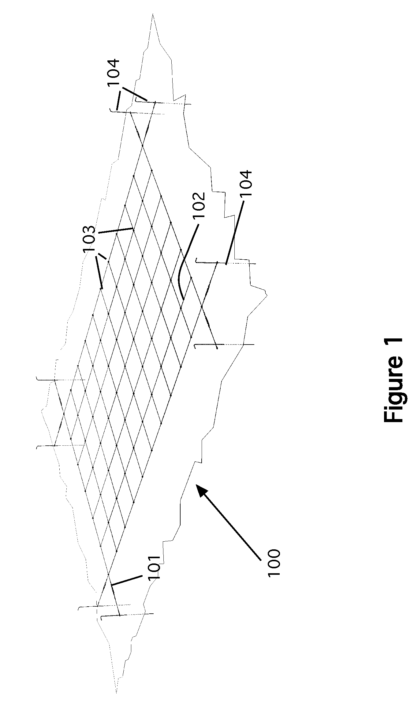
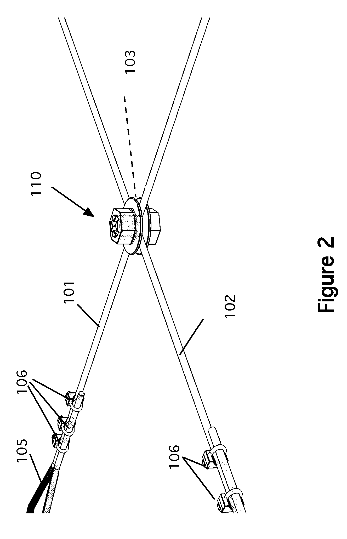
[0031]The first step in the construction of the foundation is to prepare the site and lay out the grid. Referring now to FIGS. 1-4, the grid system 100 is shown. Prior to erecting the grid, it is good practice to ensure the site is surveyed by a licensed surveyor to confirm the location of all property lines. In the preferred embodiment, the best site is one that is nearly flat with no more than a six (6) inch rise (slope) from one side of the building exterior to the other in both directions, ensuring all the foundation poles are the same length; slopes greater than six inches will require longer foundation poles. As an alternative, the site can be graded prior to construction. In the next step, level any grade high points greater than six inches or fill areas lower than six inches with crushed rock or fill material and compact so that the area is reasonably smooth and free from irregular surface changes. Next, install wood stakes at the corners of the exterior walls, tie string be...


PUM


Abstract

A method of installing a modular structure foundation system that requires no heavy equipment, minimal site preparation, and can be easily assembled by a small crew. The foundation consists of a number of box bar joists that are square units which are assembled based on a grid layout. The box bar joists are supported by foundation steel columns that are embedded into the ground. No forms or other complex structures are needed for the installation. Once the columns are installed, the box bar joists are installed using a unique leveling system. Once the box bar joists are level and secured to the columns, the foundation is complete. The use of the box bar joists also allows for expansion or contraction as additional box bar joists can easily be added or removed from the foundation. Once the box bar joists are in place, the foundation is ready for building.

Description

CROSS REFERENCE TO RELATED APPLICATIONS[0001]Not ApplicableSTATEMENT REGARDING FEDERALLY SPONSORED RESEARCH AND DEVELOPMENT[0002]Not ApplicableBACKGROUND OF THE INVENTION[0003]1. Field of the Invention[0004]This invention relates to methods of installing foundation systems and particularly to methods of installing foundation systems for modular type construction.[0005]2. Description of the Prior Art[0006]Constructing shelters has been an essential part of human development since the beginning of civilization. In the last century, buildings have been developed beyond the ordinary “stick-frame” construction into new modular designs. Both types of construction, however, use the same types of foundation, which consists of a concrete footing and some type of concrete or block walls. The building is built upon these walls typically by bolting a bottom sill plate to the top of the foundation wall using “J” bolts that have been embedded in the concrete.[0007]Although these walls have been p...

Claims


Application Information

Patent Timeline
Patent Type & Authority Patents(United States)
IPC IPC(8): E04G21/14
CPCE02D27/42
Inventor MILLER, MARTIN P.
Owner MILLER MARTIN P
Learn More