Overlay micro cell structure for universal mobile telephone system network

a micro cell and universal mobile telephone technology, applied in the field of wireless telephone networks, can solve the problems of increasing the number of subscribers, significantly increasing equipment and deployment costs, and the inability of the network operator to effectively control the access of subscribers to wireless lans, etc., and achieves the effect of increasing the capacity of the umts network and low cos

Active Publication Date: 2013-09-10
THOMSON LICENSING SA
View PDF25 Cites 12 Cited by
  • Summary
  • Abstract
  • Description
  • Claims
  • Application Information

AI Technical Summary

Benefits of technology

[0008]Briefly, there is provided a method for communicating information in a wireless network that has at least one macro cell capable of exchanging voice and data with a mobile communications device across a first wireless link, and at least one micro cell capable of communicating data at a relatively high bandwidth with the mobile communications device across a second wireless link. Typically, the micro cell has a smaller coverage area and higher capacity per user than the macro cell. Responsive to the receipt at the micro cell of an access request from a mobile terminal via the second wireless link, the micro cell communicates signaling information across a third wireless channel to the macro cell for transmission to a control element in the wireless network. The wireless network controls the micro cell in response to the signaling information. Communicating signaling information from the micro cell to the macro cell through a wireless channel advantageously avoids the need a wired back haul circuit to communicate such signaling information, thus allowing micro cell deployment at lower cost.

Problems solved by technology

Generally, without tight coupling between the UMTS network and the wireless LAN, which is a fairly costly proposition, the UMTS network operator cannot effectively control subscriber access to the wireless LAN.
However, increasing the number of access nodes significantly increases equipment and deployment costs.

Method used


Image

  • Overlay micro cell structure for universal mobile telephone system network
  • Overlay micro cell structure for universal mobile telephone system network

Examples


Embodiment Construction

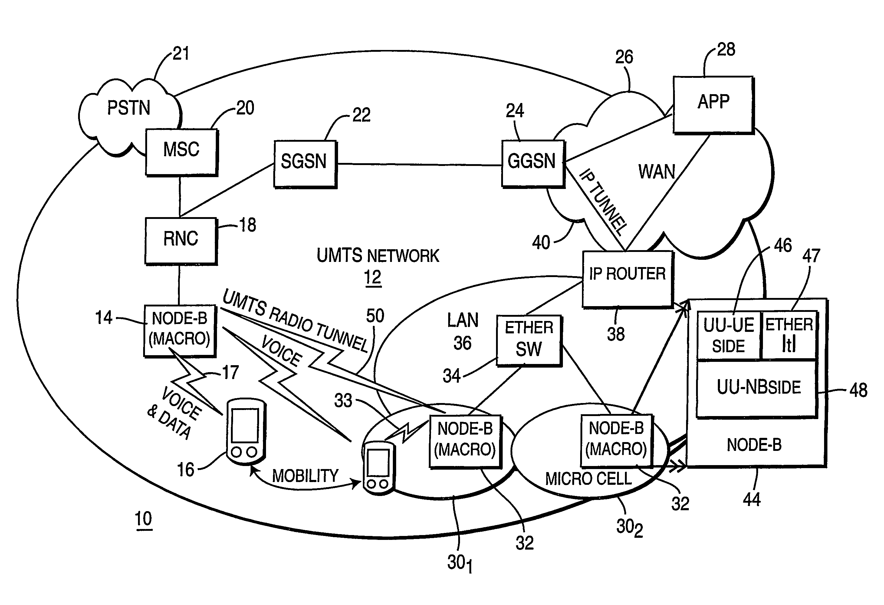
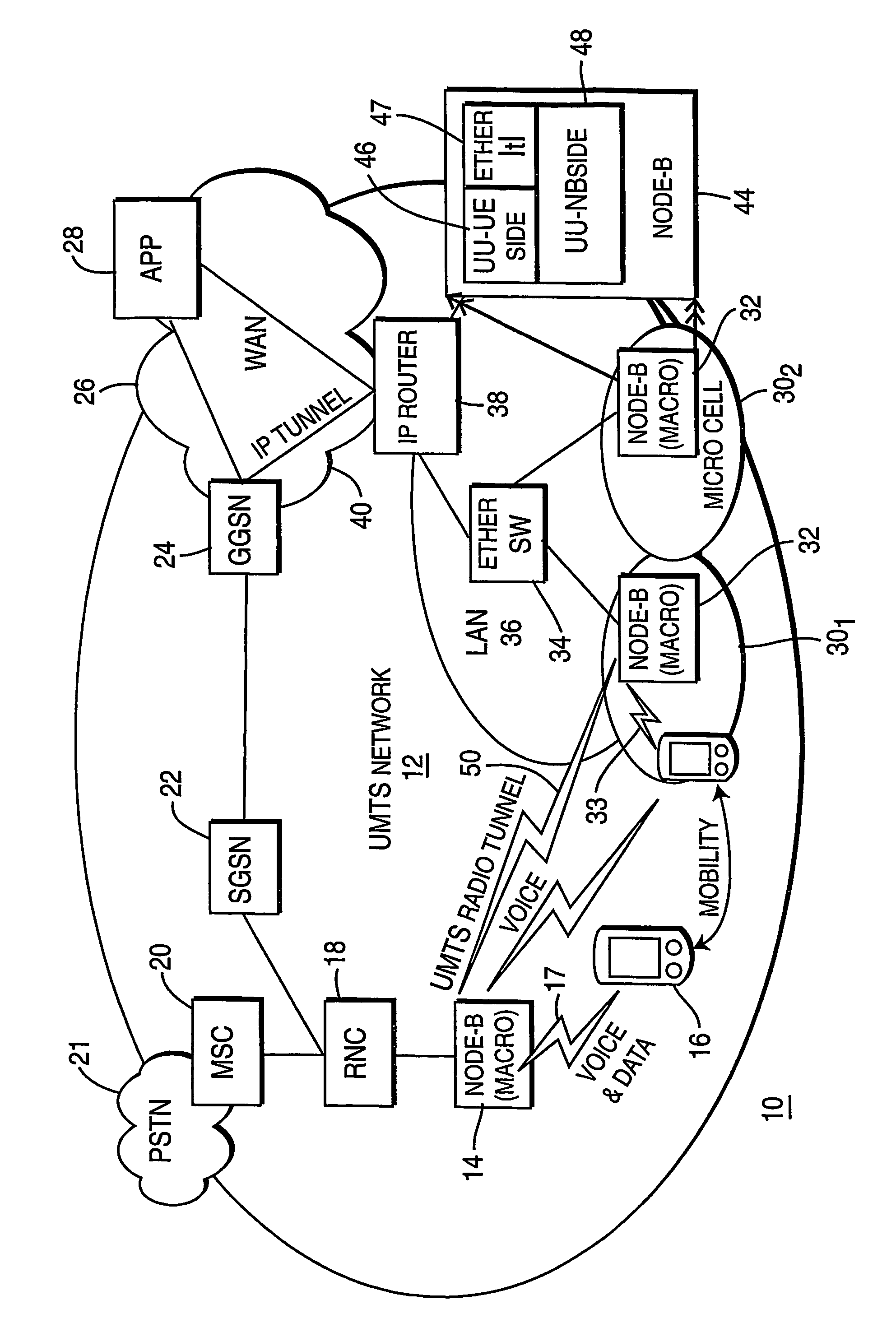
[0010]FIG. 1 illustrates a block schematic diagram of a wireless communications system 10 in accordance with a preferred embodiment of the present principles. The system 10 includes a wireless network 12, which preferably has an architecture corresponding to that described in the well-known Universal Mobile Telephone System (UMTS) standard. Accordingly, the network 12 bears the designation “UMTS network.” Within the UMTS network 12, there exists at least one, and preferably, a plurality of macro cells, each comprising a radio access node 14 which is some times referred to as a “Node B.” Each radio access node 14 includes a radio transceiver (not shown) capable of exchanging both voice and data traffic with a mobile communications device 16 across a wireless link 17. The mobile communications device 16 can include a wireless telephony handset, a wireless Personal Data Assistant (PDA) or a personal computer having a wireless modem.

[0011]Within the UMTS network 12, each radio access no...


PUM


Abstract

A wireless telephony communications system includes at least one macro cell for communicating both voice and data with a mobile communications device across a first wireless link and at least one micro cell for communicating data with the mobile communications device across a second wireless communication link. Each micro cell communicates signaling information through the macro cell via a wireless link to a control element that manages the micro cells. Using a wireless link to communicate signaling between each micro cell and the control element in the UMTS system eliminates the need for a wired back haul link, thereby reducing access costs.

Description

[0001]This application claims the benefit, under 35 U.S.C. §365 of International Application PCT / US03 / 21746, filed Jul. 11, 2003, which was published in accordance with PCT Article 21(2) on Feb. 17, 2005 in English.TECHNICAL FIELD[0002]This invention relates to a wireless telephone network that affords improved access at relatively low cost.BACKGROUND ART[0003]Wireless telephony technology continues to evolve over time. Most recently, the European Telecommunications Standards Institute (ETSI) has promulgated a new standard for mobile telephony service, known as “Universal Mobile Telecommunications Service” or UMTS which offers broadband, packet-based transmission of voice, text, video and multimedia information at rates as high as 2 Mbs. The proposed UMTS standard describes a wireless network that includes one or more radio access nodes, each typically referred to as a “Node B.” One or more Radio Network Controllers (RNC) exist within the UMTS network to manage the radio access node...

Claims


Application Information

Patent Timeline
Patent Type & Authority Patents(United States)
IPC IPC(8): H04W36/00H04W40/00H04W16/32H04W76/04H04W92/02H04W92/10H04W92/20H04W92/24
CPCH04W16/32H04W76/04H04W84/045H04W92/02H04W92/10H04W92/20H04W92/24H04W76/20
Inventor LI, JUNKEEL, ALTONGAO, WENVERMA, SHAILY
Owner THOMSON LICENSING SA
Why Eureka
Try Eureka