
Surface cleaning head

a cleaning head and surface technology, applied in the direction of carpet cleaners, floor cleaners, cleaning equipments, etc., can solve the problems of reducing the power provided to the brush, reducing the amount of material that may be entrained, and reducing the power provided to the cleaning head, so as to reduce the likelihood of clogging the flow path and reduce the power

Active Publication Date: 2013-09-17
OMACHRON INTPROP
View PDF39 Cites 27 Cited by
  • Summary
  • Abstract
  • Description
  • Claims
  • Application Information

AI Technical Summary

Benefits of technology

The surface cleaning head described in this patent allows for quick pick-up of large dirt particles and debris, such as food spills. It includes an air turbine and a dirt tray to collect dirt without blocking the airflow path. The air turbine provides sufficient power to a rotary brush, and the dirt in the tray is gradually picked up by the air traveling by the tray. The cleaning head may also have an air turbine chamber with a separate air inlet to prevent clogging, and a dirt barrier to collect dirt and slow its movement to the filtration member. Overall, this cleaning head design helps to quickly and efficiently clean large surfaces.

Problems solved by technology

In such a case, the cleaning head may be subjected to a high loading.
Due to the high loading, the airflow path in the cleaning head may become clogged reducing the airflow rate through the cleaning head and therefore reducing the amount of material that may be entrained in the airflow.
Further, if the cleaning head includes a brush driven by the air turbine, then the reduced airflow through the cleaning head will reduce the power provided to the brush and decrease the effectiveness of the brush.

Method used


Image

  • Surface cleaning head
  • Surface cleaning head
  • Surface cleaning head

Examples


Embodiment Construction

[0026]Various apparatuses or methods will be described below to provide an example of each claimed invention. No example described below limits any claimed invention and any claimed invention may cover processes or apparatuses that are not described below. The claimed inventions are not limited to apparatuses or processes having all of the features of any one apparatus or process described below or to features common to multiple or all of the apparatuses described below. It is possible that an apparatus or process described below is not an embodiment of any claimed invention.

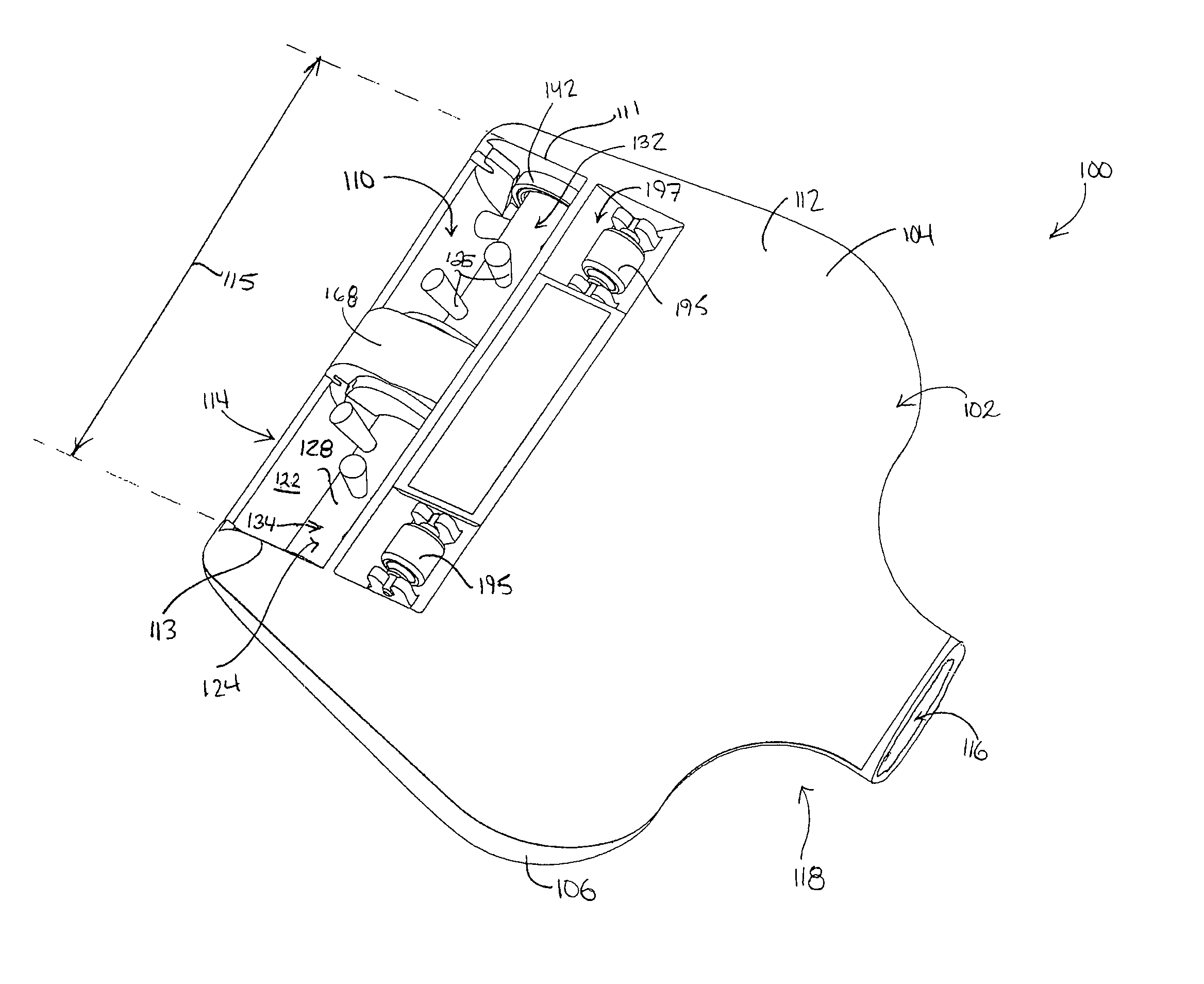
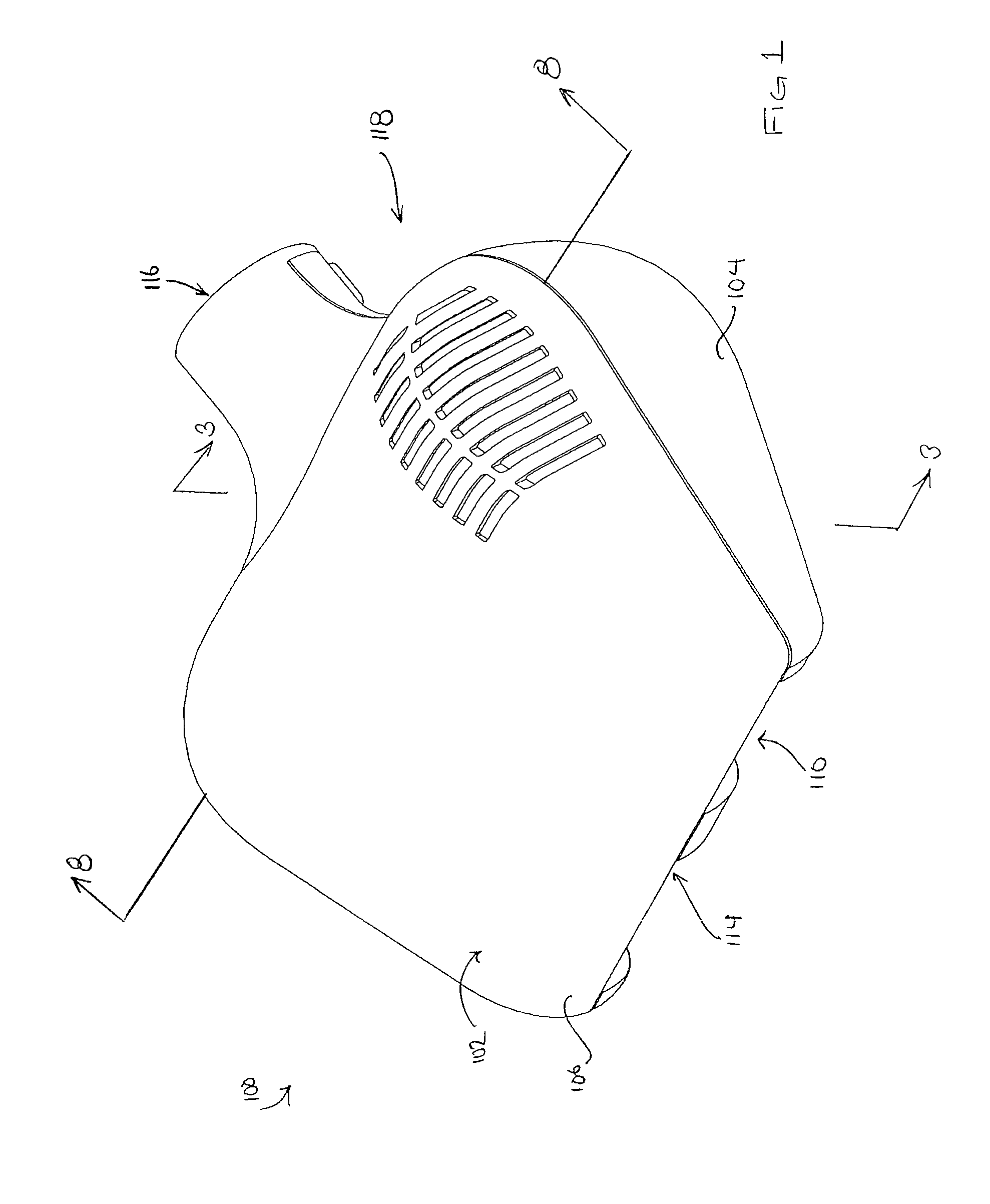
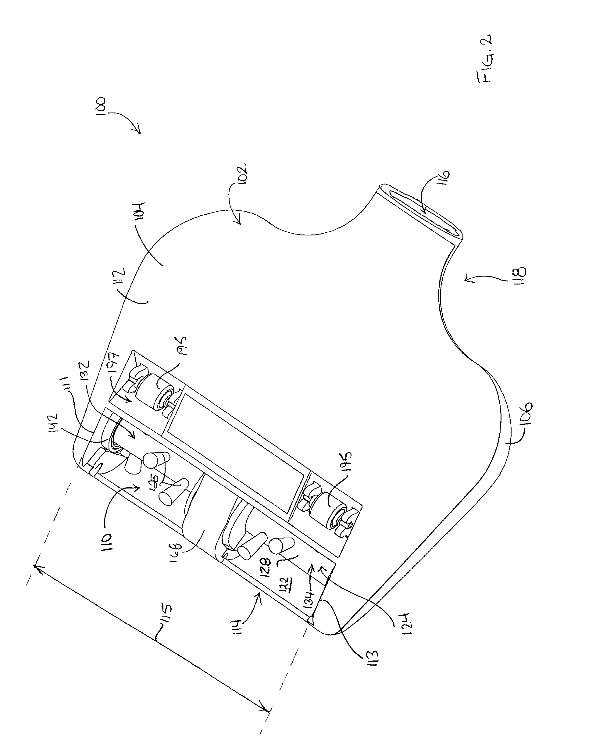
[0027]Referring to FIG. 1, an example of a surface cleaning head 100 is shown. The surface cleaning head 100 may be mounted, and preferably removably mounted, to any suitable surface cleaning apparatus (not shown), such as an upright vacuum cleaner, a canister type vacuum cleaner, a shop-vac type vacuum cleaner, a stick vac or a carpet extractor. The surface cleaning head 100 may be a main surface cleaning head ...


PUM


Abstract

A surface cleaning head, such as an auxiliary cleaning head for a vacuum cleaner, has a rotary brush associated with a dirty air inlet and driven by an air turbine. A dirt tray is positioned in the airflow path downstream of the rotary brush. In one embodiment, the air turbine is in an air turbine chamber that is not downstream from the dirty air inlet.

Description

FIELD[0001]The disclosure relates to surface cleaning heads, such as for a vacuum cleaner or other surface cleaning apparatuses. In one preferred embodiment, the disclosure relates to auxiliary surface cleaning head having a rotary brush driven by an air turbine the rotary brush and a dirt tray. In another preferred embodiment, the disclosure relates to a surface cleaning head having two air flow paths comprising a first path having an air turbine and a second path having a rotary brush driven by the air turbine and a dirt tray.INTRODUCTION[0002]The following is not an admission that anything discussed below is prior art or part of the common general knowledge of persons skilled in the art.[0003]Auxiliary surface cleaning heads are known in the art. Such cleaning heads may be stored on a vacuum cleaner and used in an above floor-cleaning mode. For example, the auxiliary cleaning head may be connected to a wand or a flexible hose of an upright vacuum cleaner for use when the main cle...

Claims


Application Information

Patent Timeline
Patent Type & Authority Patents(United States)
IPC IPC(8): A47L5/10
CPCA47L7/02A47L9/0416A47L11/4094
Inventor CONRAD, WAYNE ERNEST
Owner OMACHRON INTPROP
Learn More