Wireless communication jamming using signal delay technology

a technology of signal delay and wireless communication, applied in communication jamming, transmission monitoring, electrical equipment, etc., can solve the problems of preventing the target wireless device from communicating, interfering with the reception of target signals, and relatively inefficient, so as to reduce the complexity of electrical circuits, improve reliability, and improve the effect of signal reception

Active Publication Date: 2013-09-24
MELAMED HOWARD +1
View PDF4 Cites 50 Cited by
  • Summary
  • Abstract
  • Description
  • Claims
  • Application Information

AI Technical Summary

Benefits of technology

[0017]The advantage of the present invention over related prior art technology is that it produces a jamming signal that is 15 to 25 dB more effective than a barrage type jammer.
[0018]Another advantage of the present invention over prior art also is that it produces a jamming signal that is 10 to 15 dB more effective than a frequency specific wireless jammer.
[0019]Yet another advantage of the present invention is that it has a lower level of electrical circuit complexity than prior art barrage type wireless jammers. This results in higher reliability over this type of jammer.
[0020]Yet another advantage of the present invention is that is has a lower level of complexity than prior art frequency specific wireless jammers. This results in both higher reliability and decreased configuration complexity over this type of jammer.
[0021]Yet another advantage of the present invention over prior art reactive type jamming is that it affects an instantaneous response to short burst type communications. This is because the wireless device that is being jammed by the present invention has locked on to the false jamming signal before the short burst communications have occurred, whereas with a reactive type jammer, a jamming signal is only produced after a target signal is detected.
[0022]Yet another advantage of the present invention over prior art jammers is that because the present invention is self adjusting and tailored to the target frequencies within the jammers target frequency bands, the present invention requires a lower amount of power to affect jamming of the target signal. This results in less disruption to out of target area communications.

Problems solved by technology

This interferes with the reception of the target signal and prevents the target wireless device from communicating.
The disadvantage of a barrage type jammer is that it is relatively inefficient in that the output power of the jammer is spread across frequencies that do not require jamming.
This results in lower jamming effectiveness and increased heating of the power amplifier.
The increased heating of the power amplifier is detrimental to the reliability of the jammer.
The disadvantage of this type of system is that it must be pre-programmed with the exact frequencies that require jamming.
This pre-programming requirement increases the cost of deploying such a system.
This type of system also has the disadvantage of being less reliable over time because the specific frequencies and protocols used within a target frequency band often change.
A third disadvantage of this type of system is that the signal generation circuitry is more complex resulting in an inherent decrease in reliability.
The disadvantage of this type of jammer is that it increases the complexity to the system.
This additional complexity increases the cost of the system and decreases reliability.
Another disadvantage of the reactive type jammer is that it is not always effective against short burst communications because of the delay between the time of detection of the target signal and the commencement of the jamming signal in response.
Spread spectrum communication is inherently difficult to jam.

Method used


Image

  • Wireless communication jamming using signal delay technology
  • Wireless communication jamming using signal delay technology
  • Wireless communication jamming using signal delay technology

Examples


Embodiment Construction

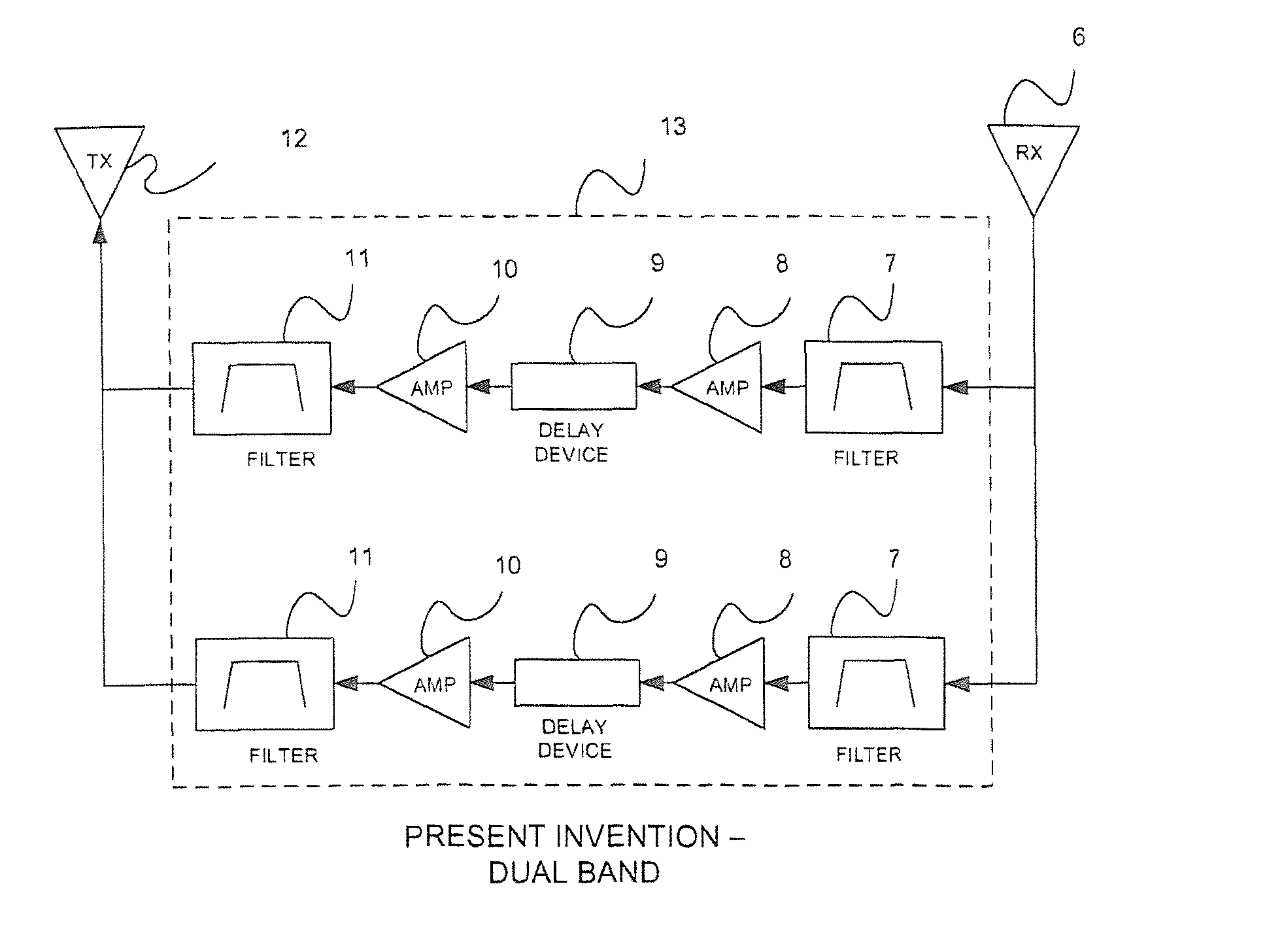
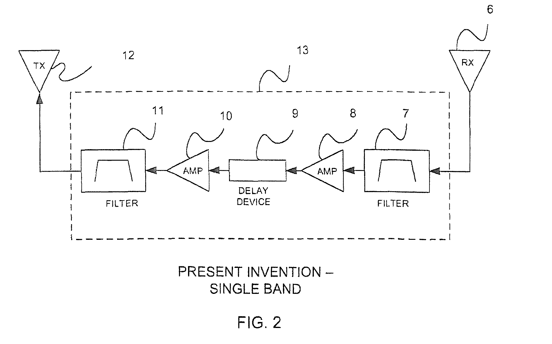
[0033]In FIG. 2, a block diagram of the present invention with a single frequency band embodiment is shown. The jammer system is comprised of the jammer 13, the jammer transmitting antenna 12, and the jammer receiving antenna 6. The jamming system operates by receiving the target downlink signal via the receiving antenna 6. The receiving antenna 6 is connected to the jamming system via RF coaxial cable which feeds through band pass filter 7. The purpose of the band pass filter 7 is to restrict and define the frequency band that is to be jammed. An example target frequency band is 1930-1990 MHz, which is the USA PCS downlink band or the 869-894 MHz frequency band which is the USA Cellular downlink frequency band. Other frequency bands are possible. The target frequency band and number of target frequency bands is dependent upon the location of the jamming system and the signals present at the jamming system location. The signal from the band pass filter 7 is fed through the RF preamp...


PUM


Abstract

A device and method for jamming wireless communication devices where the jamming signal is derived from the downlink signal of the base station and processed with a time delay sufficient length as to prevent the base station receiver from correctly processing the responding uplink signal from the targeted wireless communications device. Such wireless communication jamming device can be used by law enforcement and authorized government entities to block the operation of wireless communication devices such as cell phones within a target area.

Description

CLAIM OF PRIORITY[0001]The present application is based on and a claim of priority is made under 35 U.S.C. Section 119(e) to a provisional patent application that is currently pending in the U.S. Patent and Trademark Office, namely, that having Ser. No. 61 / 503,425 and a filing date of Jun. 30, 2011, and which is incorporated herein by reference.BACKGROUND OF THE INVENTION[0002]1. Field of the Invention[0003]The present invention relates to wireless communication jammers in environments where inhibiting wireless communications is desired and further relates to wireless communication jammers that prevent wireless communication devices such as cell phones, two way radios, smart phones, WiFi enabled computers and devices, and personal digital assistants from communicating. The category of the present invention is sometimes referred to in the prior art as wireless communications jamming, RF jamming, radio frequency jamming, cell phone blocking, and / or cell phone jamming.[0004]2. Descript...

Claims


Application Information

Patent Timeline
Patent Type & Authority Patents(United States)
IPC IPC(8): H04K3/00
CPCH04K3/43H04K3/45H04K3/46H04K3/65H04K3/42H04K2203/16H04K2203/32H04K3/41
Inventor MELAMED, HOWARDFITZSIMMONS, DANIEL
Owner MELAMED HOWARD
Why Eureka
Try Eureka