Method and system for providing a magnetoresistive structure

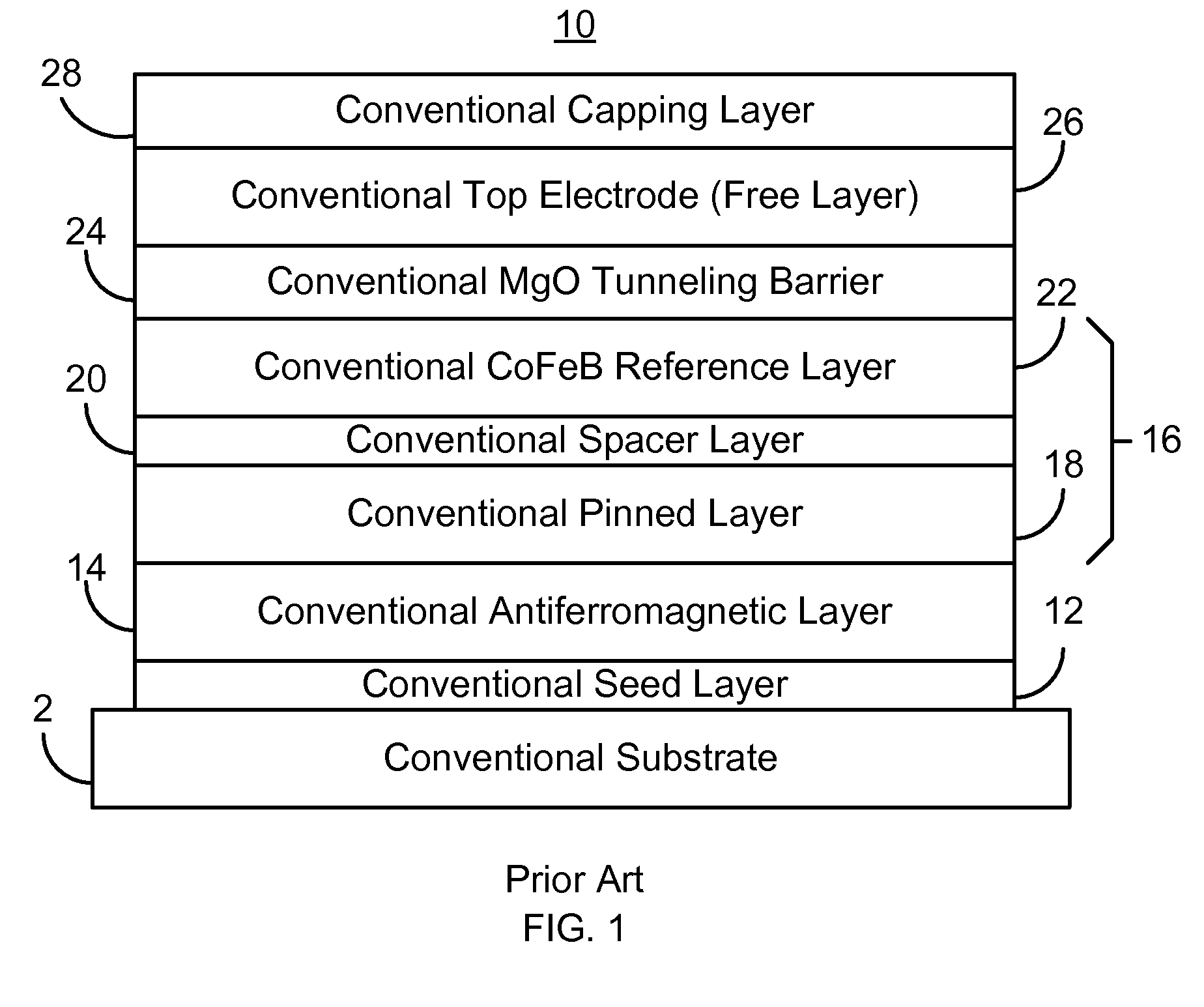
a technology of magnetoresistive structure and tunneling magnetoresistive element, which is applied in the field of conventional tunneling magnetoresistive element 10 and can solve the problems of adversely affecting the performance of the conventional tmr element b>10/b>, and affecting the properties of the conventional tmr elemen

Active Publication Date: 2013-10-01
WESTERN DIGITAL TECH INC
View PDF72 Cites 168 Cited by
  • Summary
  • Abstract
  • Description
  • Claims
  • Application Information

AI Technical Summary

Problems solved by technology

Although the conventional TMR element 10 may have the desired properties, issues with the conventional MgO tunneling barrier 24 may adversely affect the properties of the conventional TMR element 10.
Consequently, performance of the conventional TMR element 10 is adversely affected.

Method used


Image

  • Method and system for providing a magnetoresistive structure
  • Method and system for providing a magnetoresistive structure
  • Method and system for providing a magnetoresistive structure

Examples


Embodiment Construction

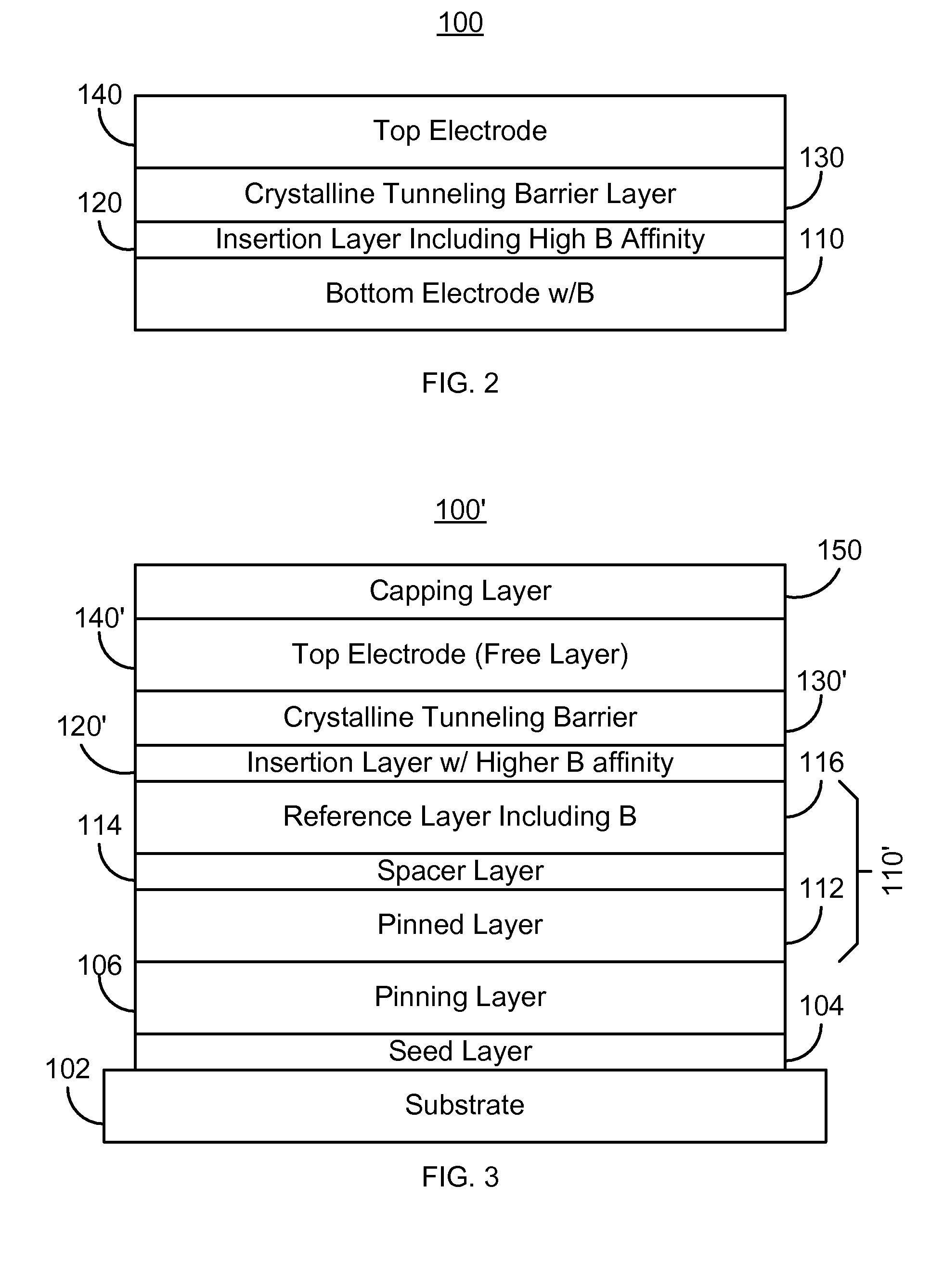
[0012]FIG. 2 depicts an exemplary embodiment of a magnetic structure 100. The magnetic structure 100 is a tunneling magnetoresistive (TMR) element. For clarity, the magnetic structure 100 is described in the context of a single TMR element. However, in another embodiment, a dual TMR element (not shown) or other analogous structure might be used. For simplicity, FIG. 2 is not drawn to scale.

[0013]The magnetic structure 100 includes a bottom electrode 110, an insertion layer 120, a crystalline tunneling barrier 130, and a top electrode 140. In one embodiment, the bottom electrode 110 is a pinned or reference layer, while the top electrode 140 is a free layer. In another embodiment, the bottom electrode 110 may be a free layer while the top electrode 140 is a pinned, or reference layer. The magnetic structure 100 is described in the context of the bottom electrode 110 being a pinned or reference layer and the top electrode 140 being a free layer.

[0014]The bottom electrode 110 is a pinn...


PUM

PropertyMeasurementUnit
thicknessaaaaaaaaaa
thicknessaaaaaaaaaa
temperatureaaaaaaaaaa

Abstract

A method and system for providing a magnetoresistive structure are described. The magnetoresistive structure includes a first electrode, an insertion layer, a crystalline tunneling barrier layer, and a second electrode. The first electrode includes at least a first magnetic material and boron. The crystalline tunneling barrier layer includes at least one constituent. The insertion layer has a first boron affinity. The at least one constituent of the crystalline tunneling barrier layer has at least a second boron affinity that is less than the first boron affinity. The second electrode includes at least a second magnetic material.

Description

BACKGROUND[0001]FIG. 1 depicts a conventional tunneling magnetoresistive (TMR) element 10 having a crystalline MgO tunneling barrier 24. For simplicity, FIG. 1 is not drawn to scale. In addition, although not shown in FIG. 1, the crystalline MgO tunneling barrier 24 could include a thin Mg or Pt layer between the bottom electrode 16 and the MgO in the tunneling barrier 24. The conventional TMR element 10 resides on a substrate 2 on which seed layer(s) 12 have been formed. The conventional TMR element 10 includes a conventional bottom electrode, or pinned layer 16. The conventional bottom electrode 16 shown is a synthetic antiferromagnet that includes magnetic layers 18 and 22 separated by a thin nonmagnetic, conductive spacer layer 20 that might include Ru. The magnetizations (not shown) of the pinned layer 18 and the reference layer 22 are substantially fixed, or pinned. The conventional TMR element 10 also includes a conventional free layer 26, or top electrode 26. The conventiona...

Claims


Application Information

Patent Timeline
Patent Type & Authority Patents(United States)
IPC IPC(8): G11B5/39H01L43/12H01F10/08
CPCH01L43/12H01F10/3295H01F41/307H01L43/08H01L43/10G11B5/3909G01R33/098H01F10/3272H10N50/85H10N50/01H10N50/10Y10T428/115Y10T428/1114Y10T428/1143
Inventor LENG, QUNWENPAKALA, MAHENDRASHEN, YONG
Owner WESTERN DIGITAL TECH INC
Why Eureka
Try Eureka