
Earth-boring bits

Inactive Publication Date: 2005-09-29
ATI PROPERTIES +1
View PDF99 Cites 187 Cited by
  • Summary
  • Abstract
  • Description
  • Claims
  • Application Information

AI Technical Summary

Benefits of technology

[0017] In the manufacture of bit bodies, hard particles and, optionally, inserts may be placed within a bit body mold. The hard particles (and any inserts present) may then be infiltrated with a molten binder, which freezes to form a solid matrix body including a discontinuous phase of hard particles within a continuous phase of binder. Embodiments of the present invention also include methods of forming articles, such as, but not limited to, bit bodies for earth-boring bits, roller cones, and teeth for rolling cone drill bits. An embodiment of the method of forming an article may comprise infiltrating a mass of hard particles comprising at least one transition metal carbide with a binder comprising at least one of nickel, iron, and cobalt and having a melting point less than 1350° C. Another embodiment includes a method comprising infiltrating a mass of hard particles comprising at least one transition metal carbide with a binder having a melting point in the range of 1050° C. to 1350° C. The binder may comprise at least one of iron, nickel, and cobalt, wherein the total concentration of iron, nickel, and cobalt is from 40 to 99 weight percent by weight of the binder. The binder may further comprise at least one of a selected transition metal carbide, tungsten carbide, tungsten, carbon, boron, silicon, chromium, manganese, silver, aluminum, copper, tin, and zinc in a concentration effective to reduce the melting point of the iron, nickel, and / or cobalt. The binder may be a eutectic or near eutectic mixture. The lowered melting point of the binder facilitates proper infiltration of the mass of hard particles.

Problems solved by technology

The bit body and other elements of earth-boring bits are subjected to many forms of wear as they operate in the harsh down hole environment.
Among the most common form of wear is abrasive wear caused by contact with abrasive rock formations.
In addition, the drilling mud, laden with rock cuttings, causes the bit to erode or wear.

Method used


Image

  • Earth-boring bits
  • Earth-boring bits
  • Earth-boring bits

Examples


Embodiment Construction

[0036] Embodiments of the present invention relate to a composition for the formation of bit bodies for earth-boring bits, roller cones, and teeth for roller cone drill bits and methods of making a bit body for an earth-boring bit, roller cones, and teeth for tri cone roller cone drill bits. Additionally, the method may be used to make other articles. Certain embodiments of a bit body of the present invention comprise at least one discontinuous hard phase and a continuous binder phase binding together the hard phase. Embodiments of the compositions and methods of the present invention provide increased service life for the bit body, teeth, and roller cones produced from the composition and method and thereby improve the service life of the earth-boring bit.

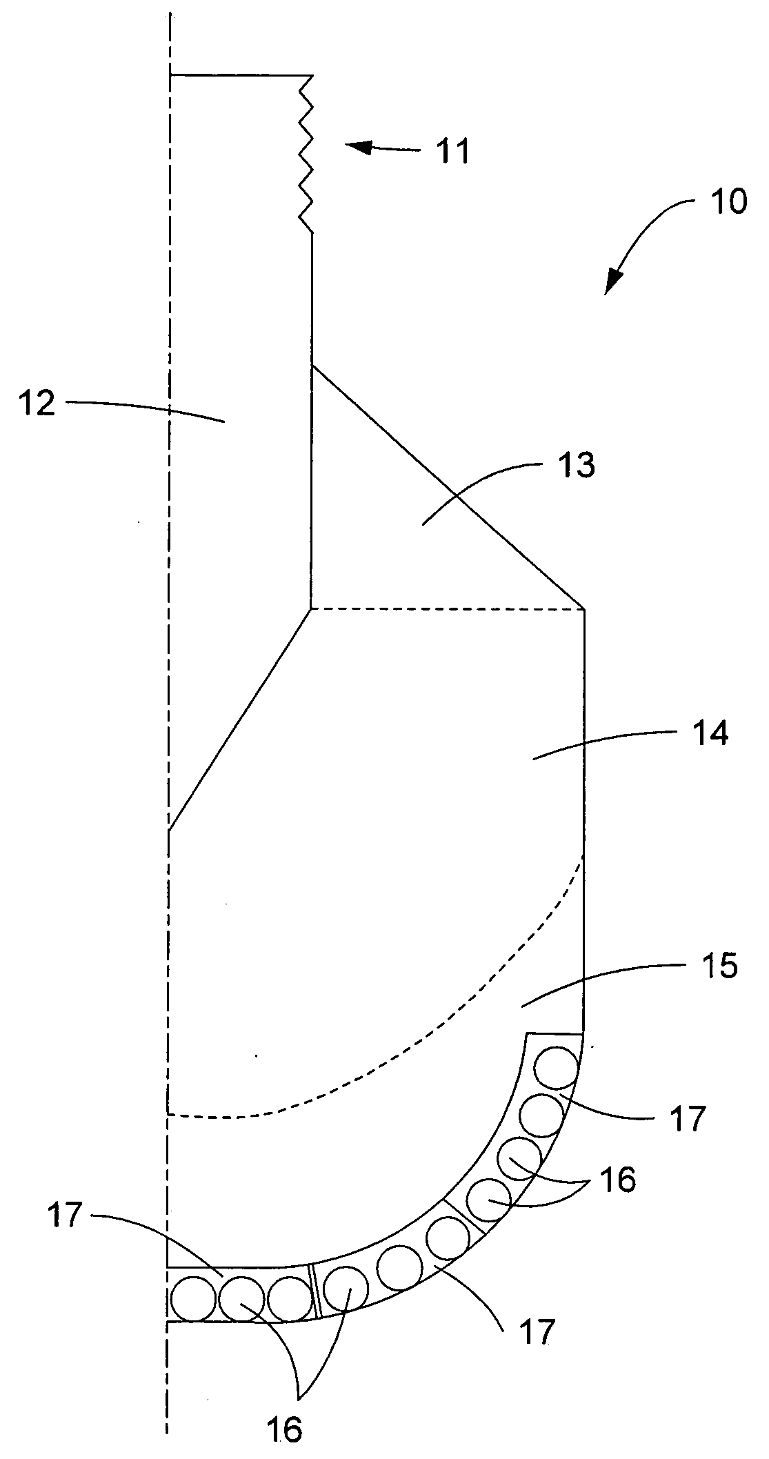
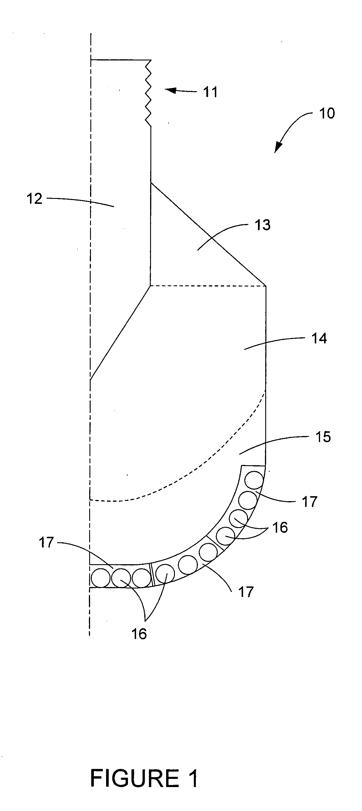
[0037] A typical bit body 10 of an earth-boring bit is shown in FIG. 1. Generally, a bit body 10 comprises attachment means 11 on a shank 12 incorporated in the bit body 10. The shank 12 is typically made of steel. A bit body may...


PUM

PropertyMeasurementUnit
Temperatureaaaaaaaaaa
Fractionaaaaaaaaaa

Abstract

The present invention relates to compositions and methods for forming a bit body for an earth-boring bit. The bit body may comprise hard particles, wherein the hard particles comprise at least one carbide, nitride, boride, and oxide and solid solutions thereof, and a binder binding together the hard particles. The binder may comprise at least one metal selected from cobalt, nickel, and iron, and at least one melting point reducing constituent selected from a transition metal carbide in the range of 30 to 60 weight percent, boron up to 10 weight percent, silicon up to 20 weight percent, chromium up to 20 weight percent, and manganese up to 25 weight percent, wherein the weight percentages are based on the total weight of the binder. In addition, the hard particles may comprise at least one of (i) cast carbide (WC+W2C) particles, (ii) transition metal carbide particles selected from the carbides of titanium, chromium, vanadium, zirconium, hafnium, tantalum, molybdenum, niobium, and tungsten, and (iii) sintered cemented carbide particles.

Description

CROSS REFERENCE TO RELATED APPLICATIONS [0001] This application is a nonprovisional application claiming priority from U.S. Provisional Application Ser. No. 60 / 556,063 filed on Apr. 28, 2004.FIELD OF TECHNOLOGY [0002] This invention relates to improvements to earth-boring bits and methods of producing earth-boring bits. More specifically, the invention relates to earth-boring bit bodies, roller cones, and teeth for roller cone earth-boring bits and methods of forming earth-boring bit bodies, roller cones, and teeth for roller cone earth-boring bits. BACKGROUND OF THE TECHNOLOGY [0003] Earth-boring bits may have fixed or rotatable cutting elements. Earth-boring bits with fixed cutting elements typically include a bit body machined from steel or fabricated by infiltrating a bed of hard particles, such as cast carbide (WC+W2C), macrocystalline or standard tungsten carbide (WC), and / or sintered cemented carbide with a binder such as, for example, a copper-base alloy. Several cutting ins...

Claims


Application Information

Patent Timeline
IPC IPC(8): C22C1/10C22C29/00C22C29/06E21B10/00E21B10/46
CPCB22F2005/001C22C29/067C22C29/005C22C1/1068B22F2998/00C22C29/00E21B10/46B22F7/06
Inventor MIRCHANDANI, PRAKASH K.EASON, JIMMY W.OAKES, JAMES J.WESTHOFF, JAMES C.COLLINS, GABRIEL B.
Owner ATI PROPERTIES
Learn More