Heat exchanger

a heat exchanger and heat shielding technology, which is applied in the direction of heat exchanger types, lighting and heating apparatus, laminated elements, etc., can solve the problems of deteriorating the basic performance of the heat exchanger, deteriorating the moisture permeability and flame retardant properties, and deteriorating the gas shielding property, so as to prevent deterioration, prevent deterioration, and maintain basic performance

Active Publication Date: 2013-10-08
PANASONIC CORP
View PDF27 Cites 38 Cited by
  • Summary
  • Abstract
  • Description
  • Claims
  • Application Information

AI Technical Summary

Benefits of technology

[0032]An object of the present invention is to provide a heat exchanger which, in an environment repeatedly subjected to dew condensation, prevents deterioration due to dew condensation water, retains the components of heat exchanger plates, and maintains basic performance such as moisture permeability, gas shielding property, and flame retardant property. Another object of the present invention is to provide a heat exchanger which, in an environment repeatedly subjected to dew condensation, prevents deterioration due to dew condensation water, prevents peeling of heat exchanger plates, maintains basic performance such as airflow leakage prevention, and improves basic performance such as ventilation resistance, sensible heat exchange efficiency, latent heat exchange efficiency, and airflow leakage.
[0034]Another aspect of the present invention is a heat exchanger which, in an environment repeatedly subjected to dew condensation, prevents deterioration due to dew condensation water, and maintains basic performance. Another aspect of the present invention is a heat exchanger which, in an environment repeatedly subjected to dew condensation, prevents deterioration due to dew condensation water, retains the components of the heat exchanger plates, and maintains basic performance such as moisture permeability, gas shielding property, and flame retardant property.
[0035]Another aspect of the present invention is a heat exchanger which, in an environment repeatedly subjected to dew condensation, prevents deterioration due to dew condensation water, prevents peeling of heat exchanger plates, and maintains basic performance such as airflow leakage prevention. Another aspect of the present invention is a heat exchanger which improves basic performance such as ventilation resistance, sensible heat exchange efficiency, and latent heat exchange efficiency.

Problems solved by technology

In an environment repeatedly subjected to dew condensation, however, the water-soluble polymeric resin impregnated or coated in the porous members therewith gradually elutes in water because of its water solubility, thereby deteriorating the gas shielding property.
Moreover, the guanidine salt-based flame retardant agent and the organic or inorganic moisture absorbent also gradually elute in water from the porous members, thereby deteriorating the moisture permeability and the flame retardant property.
As a result, the moisture permeable film becomes susceptible to peeling, pinholes, and airflow leakage, thereby degrading the basic performance of the heat exchanger.
This causes a reduction in the latent heat exchange efficiency.

Method used


Image

  • Heat exchanger
  • Heat exchanger
  • Heat exchanger

Examples


first embodiment

[0079]A first embodiment of the present invention is described as follows with reference to FIGS. 1 through 4.

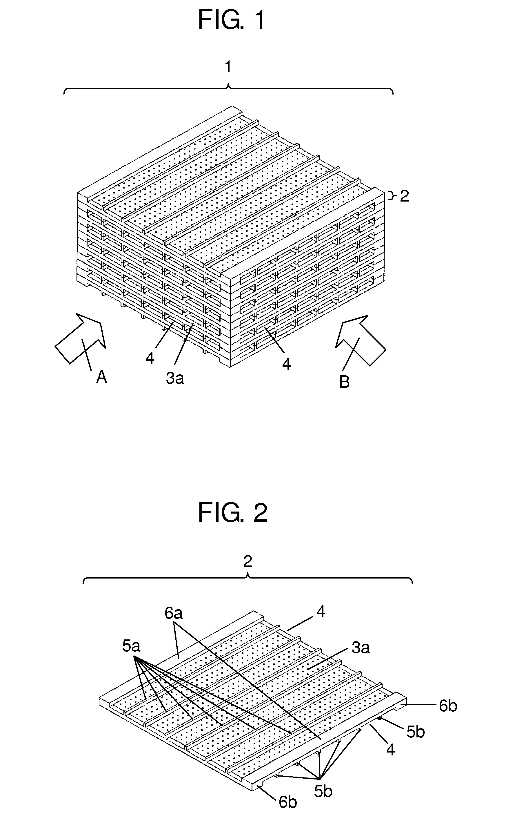
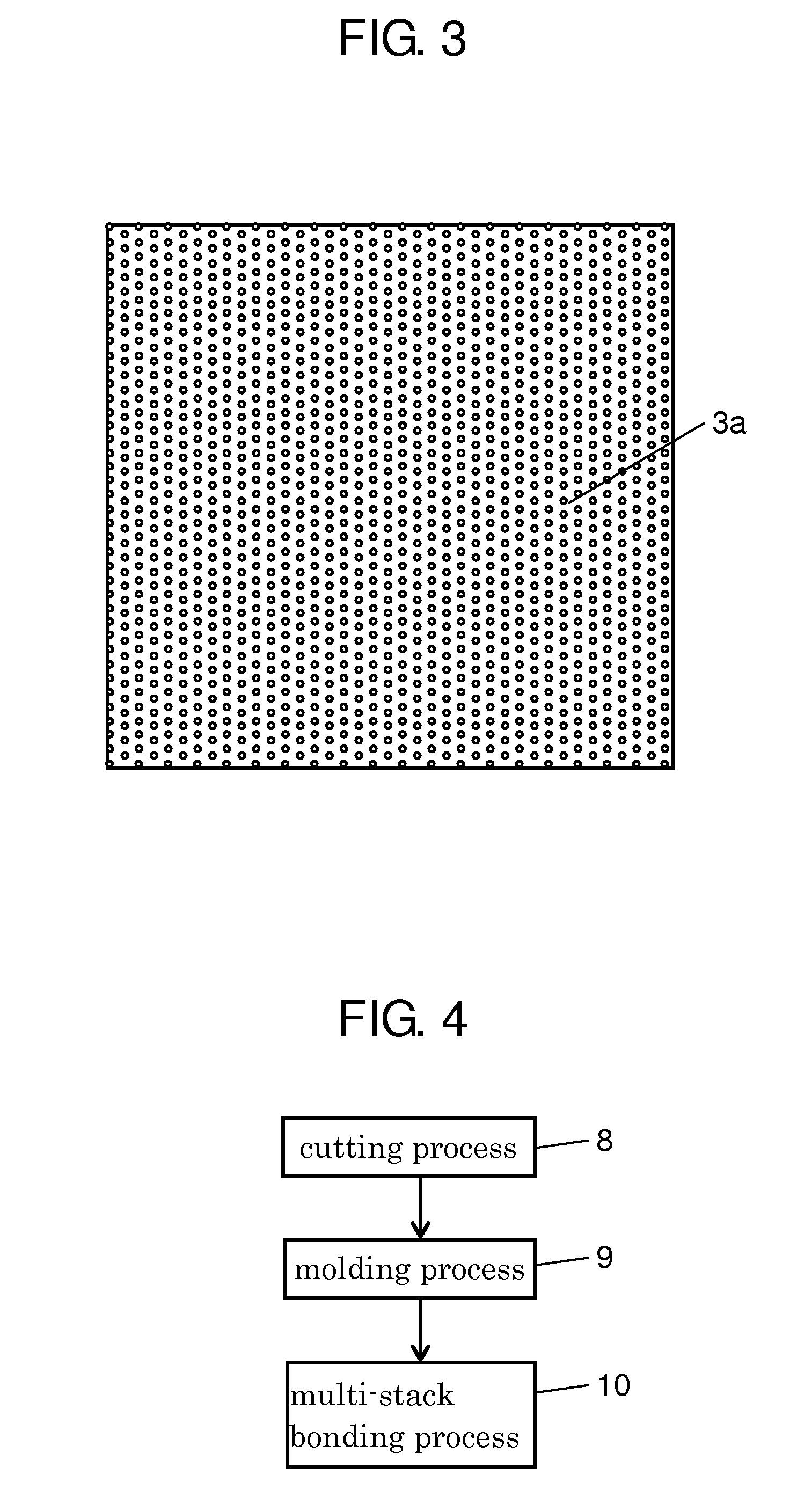
[0080]FIG. 1 is a schematic perspective view of a heat exchanger 1 of the first embodiment, FIG. 2 is a schematic perspective view of a unit device of the heat exchanger 1, FIG. 3 is a schematic plan view of a heat exchanger plate of the heat exchanger 1, and FIG. 4 is a schematic production flowchart of the heat exchanger 1.

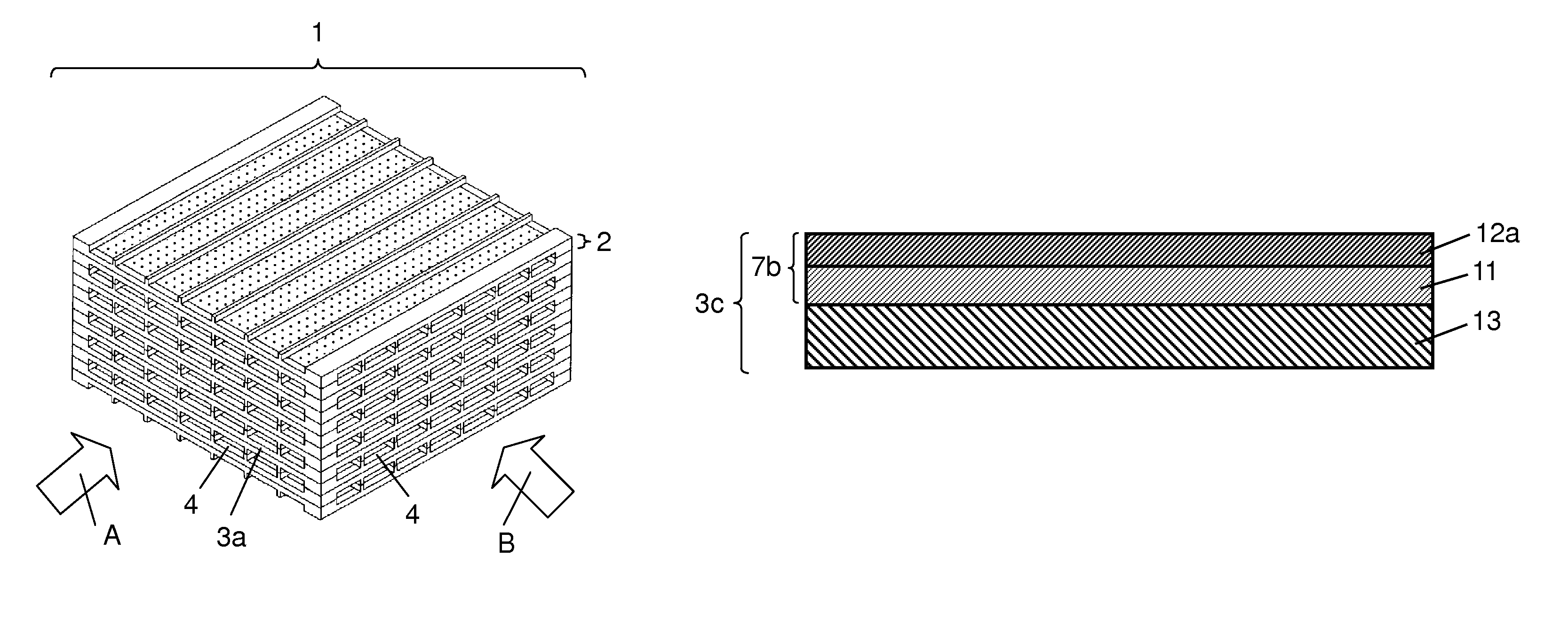
[0081]As shown in FIGS. 1, 2, and 3, the heat exchanger 1 is formed by stacking and bonding a plurality of unit devices 2 on top of each other while being rotated by 90 degrees each time. Each unit device 2 is a square 120 mm on a side and 2 mm thick and includes heat exchanger plate 3a. Heat exchanger plates 3a have airflow passages 4 through which a first airflow “A” and a second airflow “B” are made to pass in the directions of the arrows of FIG. 1. The first and second airflows “A” and “B” meet at right angles and exchange heat through heat exchanger...

second embodiment

[0101]A second embodiment of the present invention is described as follows with reference to FIG. 5. FIG. 5 is a schematic sectional view of one of heat exchanger plates 3b of a heat exchanger of the second embodiment.

[0102]Like components are labeled with like reference numerals and assumed to have the same effect as their equivalents with respect to the first embodiment, so that the description thereof is omitted.

[0103]Each heat exchanger plate 3b is a two-layer moisture permeable resin film formed by joining hydrophilic moisture permeable resin film 12a to a surface of porous resin film 11. Porous resin film 11 is water-insoluble and flame retardant. Hydrophilic moisture permeable resin film 12a has water-insolubility, flame retardant property, and gas shielding property. Porous resin film 11 is a porous sheet of PP, PE, PET, PTFE, or the like. Particularly among them, PTFE (polytetrafluoroethylene) is preferable because it has small pores, a high porosity, a small thickness, sta...

third embodiment

[0110]A third embodiment of the present invention is described as follows with reference to FIGS. 6 and 7. FIG. 6 is a schematic sectional view of one of heat exchanger plates 3c of a heat exchanger of the third embodiment, and FIG. 7 is a schematic sectional view of one of heat exchanger plates 3d of the heat exchanger.

[0111]Like components are labeled with like reference numerals and assumed to have the same effect as their equivalents with respect to the first and second embodiments, so that the description thereof is omitted. Heat exchanger plate 3c of FIG. 6 is a three-layer composite moisture permeable resin film consisting of two-layer moisture permeable resin film 7b of the second embodiment and porous resin substrate 13, which is breathable, water-insoluble, and flame retardant. The three-layer composite moisture permeable resin film is more specifically formed by joining hydrophilic moisture permeable resin film 12a having water-insolubility, flame retardant property, and ...


PUM

PropertyMeasurementUnit
anglesaaaaaaaaaa
thickaaaaaaaaaa
thickaaaaaaaaaa

Abstract

A heat exchanger, which maintains basic performance even in an environment repeatedly subjected to dew condensation, is provided. The heat exchanger is formed of a plurality of unit devices each including a heat exchanger plate, spacer ribs, and shielding ribs. The heat exchanger plate, the spacer rib and the shielding rib are integrally molded with resin. The spacer ribs keep the spacing between the heat exchangers, and the shielding ribs shield leakage of airflow. The unit devices are stacked each other to form airflow passages between the heat exchanger plates. The airflow passages allow a first airflow and a second airflow to pass therethrough and to exchange heat through the heat exchanger plates. The heat exchanger plate is made of a moisture permeable resin film having water-insolubility and flame retardant property, and the resin has water-insolubility and flame retardant property.

Description

TECHNICAL FIELD[0001]The present invention relates to a lamination type heat exchanger for use in a heat exchange type ventilation fan for domestic use or in a total heat exchange type ventilator for buildings or the like. The invention more particularly relates to a heat exchanger that can be used in an environment repeatedly subjected to dew condensation.BACKGROUND ART[0002]Some well-known conventional heat exchangers of this type are cross flow type heat exchangers using a corrugation process (see, for example, Patent Document 1 below).[0003]Referring to the schematic perspective view of FIG. 8, a conventional heat exchanger 104 will be described.[0004]As shown in FIG. 8, heat exchanger 104 includes a plurality of heat exchanger blocks 101 each having a heat exchanger plate 102 and a corrugated spacer plate 103 bonded thereto. The heat exchanger plate 102 is made of paper treated with a hydrophilic polymer containing a moisture absorbent such as lithium chloride. The heat exchang...

Claims


Application Information

Patent Timeline
Patent Type & Authority Patents(United States)
IPC IPC(8): F28F3/00
CPCF24F3/147F28D9/0062F28F3/025F28F21/065F28F19/04Y10T29/4935F28F2245/02
Inventor MURAYAMA, TAKUYASUGIYAMA, MAKOTO
Owner PANASONIC CORP
Why Eureka
Try Eureka