Fastening of rotor magnets on the shaft of a compressor arrangement

a compressor arrangement and rotor magnet technology, applied in sea energy generation, dynamo-electric machines, tidal stream/damless hydropower, etc., to achieve the effect of reducing fuel consumption and improving the energy balance of the combustion engin

Active Publication Date: 2013-10-08
LINDENMAIER +1
View PDF36 Cites 5 Cited by
  • Summary
  • Abstract
  • Description
  • Claims
  • Application Information

AI Technical Summary

Benefits of technology

[0088]The control of the motor / generator operation for the first time permits the immediate, targeted closed-loop control of the charging procedure. Since the electric motor is preferably controlled with a closed loop via a frequency converter, the rotational speed of the compressor as well as of the turbine wheel and thus of the air mass flow may be determined in an exact manner. The control of the charging procedure of the combustion engine is preferably integrated into the central motor control. With this, it is possible to realise a charging controlled by the characteristic field. Thus an exact matching and optimisation of the combustion parameters (fuel quantity, air quantity, charging pressure, exhaust gas return rate, ignition point in time, etc) is possible, by which means a significant reduction in fuel consumption is achieved. This thus represents an active characteristic field extension, by which means the energy balance of the combustion engine may be considerably improved. This closed-loop control circuit permits the control and optimisation of the complete combustion procedure within the combustion space of an internal combustion engine.

Problems solved by technology

However, with such types of charged internal combustion machines, there exists the problem of the so-called “turbo-hole” which in particular occurs when starting up and accelerating from low rotation speeds of a vehicle, thus when the internal combustion engine is to be rapidly increased in the region of higher power.
This is due to the fact that the increased air quantity requirement on the air intake side may only be provided with a delay (amongst other things caused by the inertia of the system of the turbine wheel and compressor wheel).

Method used


Image

  • Fastening of rotor magnets on the shaft of a compressor arrangement
  • Fastening of rotor magnets on the shaft of a compressor arrangement
  • Fastening of rotor magnets on the shaft of a compressor arrangement

Examples


Embodiment Construction

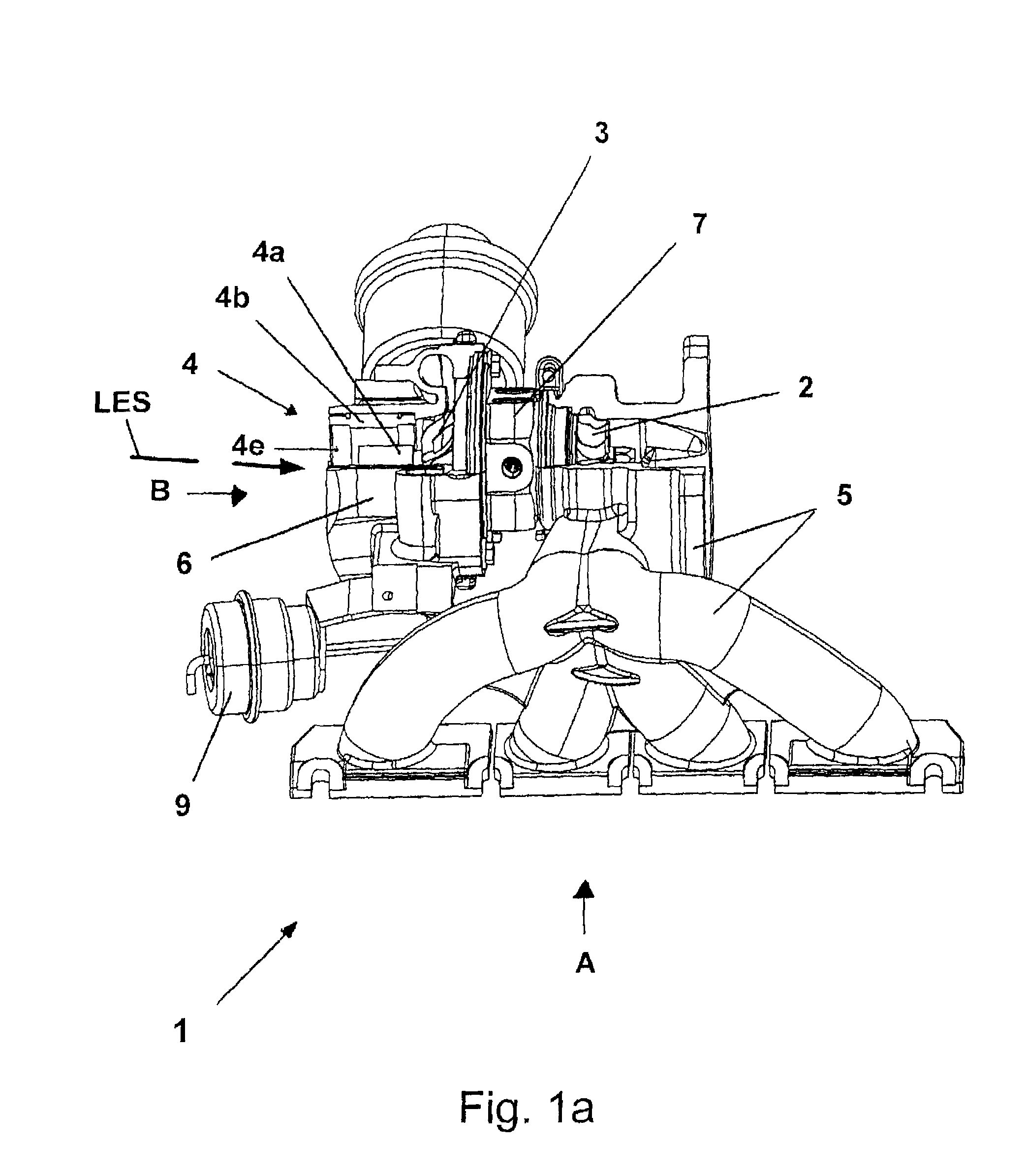
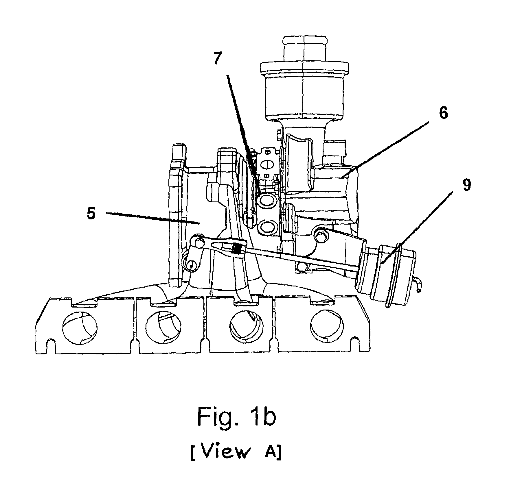
[0105]The basics of the invention are to be shown hereinafter by way of the first embodiment form according to FIGS. 1a to 1d.

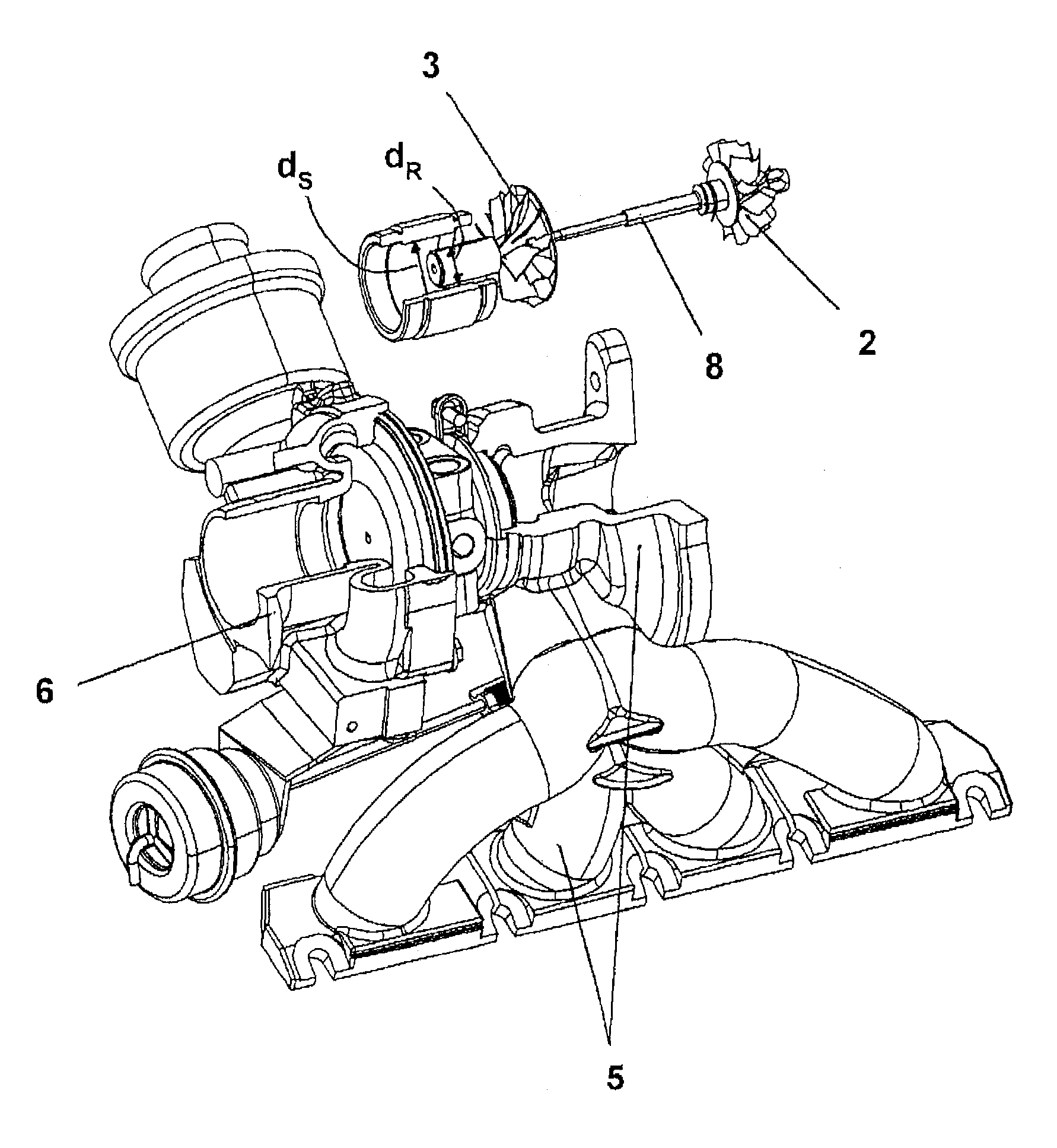
[0106]FIGS. 1a to 1d show an electrically modified mechanical turbocharger 1, which may be coupled with a turbine housing 5, onto an internal combustion engine. After combustion, the exhaust gas is collected by the exhaust manifold shown in FIG. 1a and is used for driving the turbine wheel 2. The turbine wheel 2 is surrounded by the turbine housing 5 and is essentially taken from a conventional mechanical turbocharger. A bearing housing 7 connects to the turbine housing 5, and then a compressor housing 6. A compressor wheel is attached in this compressor housing 6, and the air fed through an inlet opening (this inlet opening is to be seen particularly well in FIG. 1c) is compressed by way of a compressor wheel 3 and is led in a manner which is not represented here, to the combustion space of the internal combustion engine. The compressor wheel 3 in FIG. 1a o...


PUM


Abstract

A compressor arrangement for compressing fresh air for internal combustion engines includes a compressor wheel and an electric motor having at least one stator and at least one rotor having a rotor magnet and a rotor gap between the rotor and stator. The rotor gap is designed such that when the compressor wheel rotates, at least 50%, of the air mass flow to be compressed is fed through the rotor gap. The compressor wheel is mounted on a shaft or contains the shaft and at least one rotor magnet or a carrier for holding the rotor magnet and is mountable as a separate part on said shaft and may be bolted, splinted, glued, shrunk, or secured by form-fit to said shaft to prevent rotation.

Description

[0001]This Application is a National Phase application of PCT Application Ser. No. PCT / EP2008 / 003197 filed on Apr. 15, 2008 which claims priority to: (1) PCT Appln. Ser. No. PCT / EP2007 / 009446 filed on Oct. 25, 2007; (2) PCT Appln. Ser. No. PCT / EP2007 / 009445 filed on Oct. 25, 2007; (3) EP Patent Appln. Ser. No. 07 090 100.4 filed on May 24, 2007; (4) EP Patent Appln. Ser. No. 07 075 981.6 filed on May 24, 2007; (5) EP Patent Appln. Ser. No. 07 075 496.5 filed on Jun. 20, 2007; (6) EP Patent Appln. Ser. No. 07 075 661.4 filed on Aug. 1, 2007; (7) U.S. patent application Ser. No. 11 / 781,644 filed on Jul. 23, 2007; (8) U.S. patent application Ser. No. 11 / 781,684 filed on Jul. 23, 2007; (9) U.S. patent application Ser. No. 11 / 915,350 filed on Nov. 23, 2007; and (10) U.S. patent application Ser. No. 11 / 915,353 filed on Nov. 23, 2007.FIELD OF INVENTION[0002]The invention relates to a compressor arrangement, in particular to a turbocharger.BACKGROUND INFORMATION[0003]Internal combustion mac...

Claims


Application Information

Patent Timeline
Patent Type & Authority Patents(United States)
IPC IPC(8): F04B39/06
CPCF01D5/025F02B37/025F04D25/0606H02K7/14H02K7/1823F04D25/024F01N13/107F02B39/10H02K9/06Y02E10/28Y02T10/144F05D2220/40F05D2220/768Y02E10/30Y02T10/12Y02E10/20
Inventor GOEDECKE, HOLGERLOEFFLER, RUDOLFHEBER, RALFBISCHOF, THOMASMAIER, SANDRAKAEMPFER, OLIVER
Owner LINDENMAIER
Why Eureka
Try Eureka