Particle beam irradiation apparatus and control method of the particle beam irradiation apparatus

a particle beam irradiation and control method technology, applied in the field control method of particle beam irradiation apparatus, can solve the problems of generating radioactive waste after therapeutic irradiation, limiting the influence of normal cells around the affected area, and not being able to precisely three-dimensional adjust the beam, etc., to achieve highly sensitive measurement of leakage dose and reliable measurement of beam dos

Active Publication Date: 2013-10-08
NAT INST FOR QUANTUM & RADIOLOGICAL SCI & TECH +1
View PDF17 Cites 46 Cited by
  • Summary
  • Abstract
  • Description
  • Claims
  • Application Information

AI Technical Summary

Benefits of technology

[0025]According to the particle beam irradiation apparatus and the control method of the particle beam irradiation apparatus of the present invention, highly reliable measurement of a dose of each beam is possible, and highly sensitive measurement of a leakage dose caused by momentary beam emission is possible.

Problems solved by technology

However, the broad beam method is not capable of precise three-dimensional adjustment of the beam in accordance with the shape of the affected area, and there is a limit to reducing the influence on the normal cells around the affected area.
The geometric collimator and the compensator are created for each affected area (and for each irradiation direction relative to the affected area), and there is a problem that radioactive wastes are generated after therapeutic irradiation.
A weak point of the spot scanning irradiation is that the beam emission cannot be actually immediately terminated even if the beam emission control apparatus outputs the beam termination command.
This is particularly a problem when the irradiation dose (set dose) for each point is small, because a ratio of the leakage dose (leakage dose / set dose) is large.
However, the reduction in the beam intensity leads to an increase in the time for treatment, and a physical burden of the patient increases.
Therefore, the irradiation points are relatively deviated along with the movement of the region caused by respiration, and a dose distribution becomes non-uniform.

Method used


Image

  • Particle beam irradiation apparatus and control method of the particle beam irradiation apparatus
  • Particle beam irradiation apparatus and control method of the particle beam irradiation apparatus
  • Particle beam irradiation apparatus and control method of the particle beam irradiation apparatus

Examples


first embodiment

(3) First Embodiment

Second Abnormality Determination (Part 1)

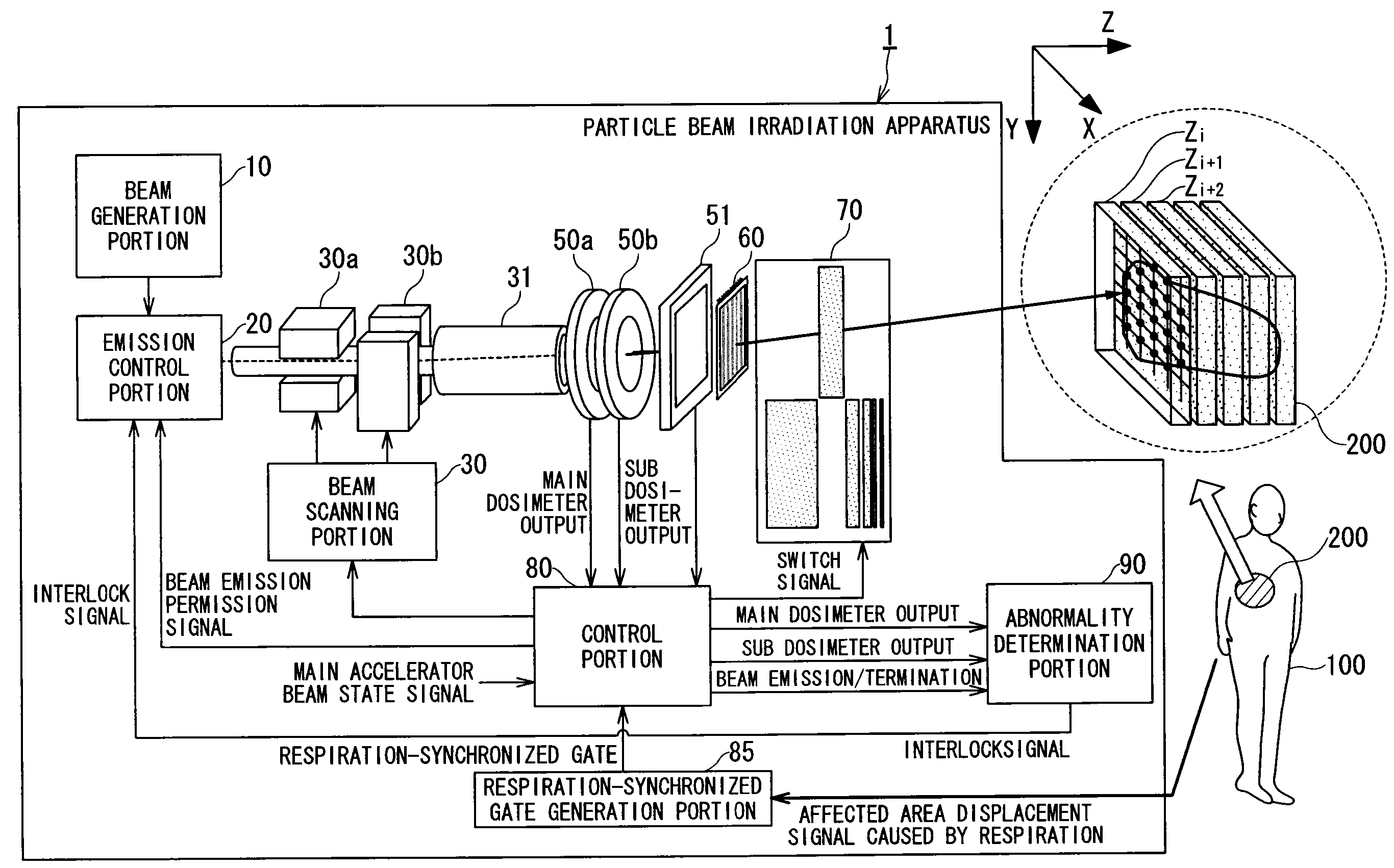
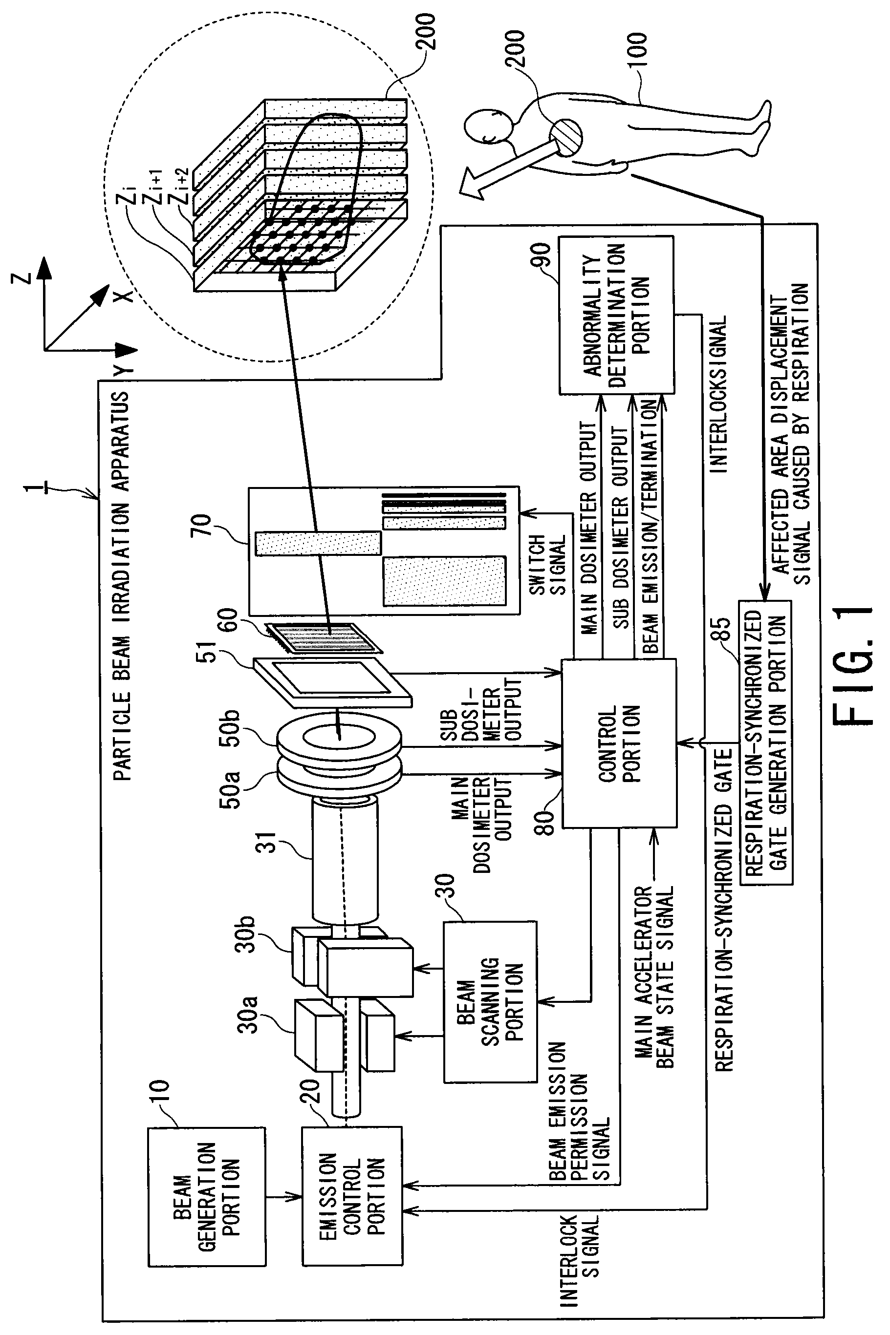
[0086]FIG. 9 is a block diagram mainly showing an example of configuration of the abnormality determination portion 90 according to the first embodiment. The abnormality determination portion 90 according to the first embodiment includes a second main dosimeter counter 95, a second sub dosimeter counter 94, and a second abnormality determination portion 96, in addition to the configuration of the conventional abnormality determination portion 900 (FIG. 4).

[0087]Although the second main dosimeter counter 95 counts the number of pulses output from the main dosimeter 50a during the beam emission as in the main dosimeter counter 81, the integration period of the counter is smaller than that of the main dosimeter counter 81.

[0088]Although the second sub dosimeter counter 94 counts the number of pulses output from the sub dosimeter 50b during the beam emission as in the sub dosimeter counter 91, the integration period of the cou...

second embodiment

(4) Second Embodiment

Second Abnormality Determination (Part 2)

[0099]Abnormality determination according to a second embodiment is performed in parallel with the abnormality determination in the first embodiment (the first abnormality determination and the second abnormality determination (part 1)). Specifically, it is determined that there is an abnormality when an absolute value of a difference between the count value a3 of the second main dosimeter counter 95 and the count value b3 of the second sub dosimeter counter 94 exceeds a predetermined threshold. The main dosimeter 50a and the sub dosimeter 50b usually have the same configuration. Therefore, if the main dosimeter 50a and the sub dosimeter 50b are both normal, the same number of pulses would be measured. Consequently, it is determined that there is an abnormality in one of the main / sub dosimeters 50a and 50b or one of the second main / sub dosimeter counters 95 and 94 if the absolute value of the difference between the count ...

third embodiment

(5) Third Embodiment

Second Abnormality Determination (Part 3)

[0101]FIG. 13 is a diagram showing an example of configuration of an abnormality determination portion 90b according to a third embodiment. Third main / sub dosimeter counters 98 and 97 as well as a third abnormality determination portion 99 that performs leakage dose determination are added to the abnormality determination portion 90 of the first and second embodiments to form the abnormality determination portion 90b.

[0102]The third abnormality determination portion 99 compares count values a4 (third sectional dose measurement value) and b4 (fourth sectional dose measurement value) of pulses (pulses caused by leakage dose) output from the third main / sub dosimeter counters 98 and 97 during the termination of the beam emission with preset count values A4 (third reference value) and B4 (fourth reference value) for third abnormality determination defined in a pattern file 40b, respectively. If the count value exceeds the pres...


PUM


Abstract

Provided is a particle beam irradiation apparatus capable of highly reliable measurement of a dose of each beam and capable of highly sensitive measurement of a leakage dose caused by momentary beam emission. The particle beam irradiation apparatus according to the present invention includes: an emission control portion that controls emission and termination of a particle beam; a control portion that sequentially changes an irradiation position of the particle beam relative to an affected area; first and second dosimeters that measure dose rates of the particle beam directed to the affected area; and an abnormality determination portion that accumulates the dose rates output from the first and second dosimeters for each of predetermined determination periods to calculate first and second sectional dose measurement values and that performs second abnormality determination of determining that there is an abnormality and outputs an interlock signal for terminating the emission of the particle beam in at least one of a case in which the first sectional dose measurement value exceeds a predetermined first reference range and a case in which the second sectional dose measurement value exceeds a predetermined second reference range.

Description

TECHNICAL FIELD[0001]The present invention relates to a particle beam irradiation apparatus and a control method of the particle beam irradiation apparatus, and particularly for directing a heavy particle beam of carbon, a proton beam, or the like to an affected area to treat cancer.BACKGROUND ART[0002]Today, cancer is the highest cause of death, and more than 300,000 people die of cancer every year. Under the circumstances, a particle radiation therapy using a carbon beam and a proton beam with excellent features of high therapeutic effects and few side effects is drawing attention. In the therapy, a particle beam emitted from an accelerator can be directed to cancer cells to destroy the cancer cells while reducing influence on normal cells.[0003]In the therapeutic method, a currently used particle beam irradiation method is a method called a broad beam method. In the broad beam method, a diameter of the particle beam is expanded to a size greater than the affected area based on a ...

Claims


Application Information

Patent Timeline
Patent Type & Authority Patents(United States)
IPC IPC(8): A61N5/10
CPCA61N5/1043G21K1/025A61N5/1071A61N2005/1087A61N2005/1074
Inventor HANAWA, KATSUSHIISEKI, YASUSHIKAKUTANI, NOBUKAZUFURUKAWA, TAKUJIINANIWA, TAKUSATO, SHINJINODA, KOUJI
Owner NAT INST FOR QUANTUM & RADIOLOGICAL SCI & TECH
Why Eureka
Try Eureka