
Photostimulable plate reading device

a technology of photostimulable plates and reading devices, which is applied in the direction of material analysis using wave/particle radiation, instruments, x/gamma/cosmic radiation measurement, etc., can solve the problems of affecting the efficiency of cr readers, it takes several seconds to read the whole psp, etc., and achieves the effect of reducing the time taken for reading

Active Publication Date: 2013-10-15
CARESTREAM DENTAL TECH TOPCO LTD
View PDF17 Cites 2 Cited by
  • Summary
  • Abstract
  • Description
  • Claims
  • Application Information

AI Technical Summary

Benefits of technology

Significantly increases reading efficiency and reduces time by allowing 1000000 times more blue light to pass than red light, facilitating faster and more accurate image data collection.

Problems solved by technology

This is detrimental to the efficiency of the CR reader.
A drawback of this reading method is that it takes several seconds to read the whole PSP.

Method used


Image

  • Photostimulable plate reading device
  • Photostimulable plate reading device
  • Photostimulable plate reading device

Examples


first embodiment

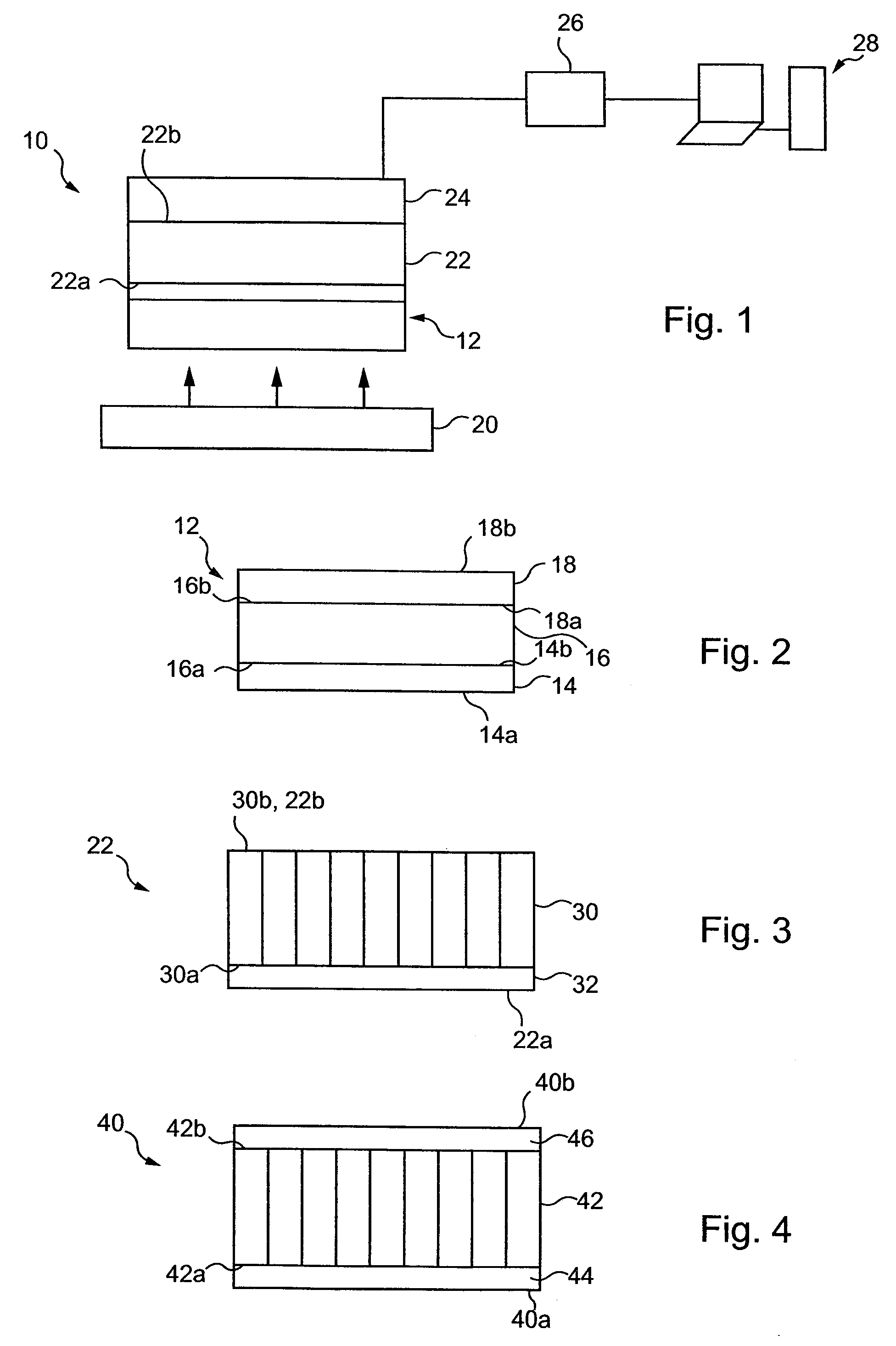
[0103]In a first embodiment illustrated in FIG. 3, the block 30 may be coated with one filtering unit 32 unit.

[0104]This single filtering unit acts as a selective coating for reflecting or absorbing stimulating light (light emitted in the first wavelength range) and transferring light converted by the photostimulable plate 12 and carrying image data (light emitted in the second wavelength range).

[0105]In a preferred embodiment, photostimulable plate 12 is arranged above filtering means 22 and detector 24 contrary to the arrangement of FIG. 1.

[0106]Filtering unit 32 is disposed on the surface 30a of the block 30 facing the incoming light.

[0107]More particularly, filtering unit 32 is for example coated on the surface 30a through a known coating process.

[0108]The filtering unit 32 is a thin multilayered filter comprising a plurality of superimposed layers with different refractive indices and assembled all together. The layers are for example glass layers.

[0109]Each layer enables the l...

second embodiment

[0122]In a second embodiment illustrated in FIG. 4, two filtering units 44 and 46 may be respectively associated with the two opposite surfaces 40a and 40b of a block of optical fibers 42 for filtering out a predetermined light wavelength range.

[0123]This block may be identical to block 30 in FIG. 3.

[0124]In particular, each filtering unit prevents light emitted in the first wavelength range from passing and allows light emitted in the second wavelength range to pass.

[0125]When two filtering units are provided each of them may be designed so as to filter out a predetermined proportion of undesired light.

[0126]Thus, the resulting efficiency of both filtering units substantially allows the whole undesired light to be rejected.

[0127]It is noted that the FIG. 4 embodiment may find applications where the filtering efficiency is to be enhanced with respect to the filtering efficiency of the FIG. 3 embodiment.

[0128]The filtering units 44, 46 are for example coated on the opposite surfaces ...


PUM

PropertyMeasurementUnit
refractive indexaaaaaaaaaa
thicknessaaaaaaaaaa

Abstract

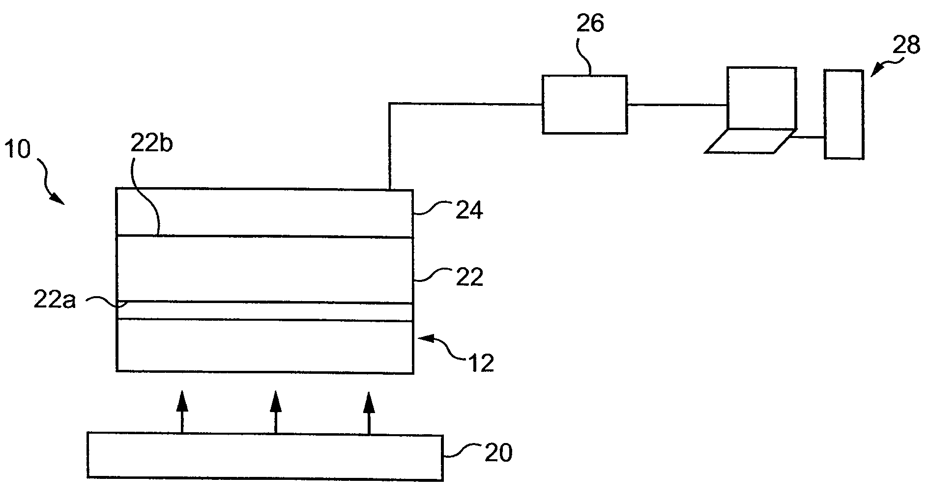
A photostimulable plate reading device. The device includes: at least one photostimulable plate carrying image data and having two opposite surfaces; an illuminator for homogeneously illuminating a first one of the two opposite surfaces of the at least one photostimulable plate with light emitted in a first wavelength range, the illumination causing the at least one photostimulable plate both to emit light in a second wavelength range by photostimulated luminescence and to scatter light in the first wavelength range; a filter for preventing the light scattered in the first wavelength range from passing and for allowing the light emitted in the second wavelength range to pass, the filter facing a second one of the two opposite surfaces of the at least one photostimulable plate; and a detector composed of a two dimensional array of pixels for detecting the light allowed to pass and for obtaining image data therefrom.

Description

FIELD OF THE INVENTION[0001]Devices and methods consistent with the present invention relate to photostimulable plate reading devices and methods for reading photostimulable plates.BACKGROUND OF THE INVENTION[0002]A photostimulable plate, also referred to as Photostimulable Storage Phosphor (PSP), is to detect image data relating to an object / human body which is exposed to X-rays. The method of radiographic image acquisition using a PSP will be referred to as CR (for Computed Radiography) in the following.[0003]The photostimulable plate or PSP comprises a substrate which serves as a support for a phosphor layer on top of which is coated a protective layer.[0004]In particular, a CR system includes an X-rays controlled source which illuminates an object with X-rays and a photostimulable plate or PSP disposed behind the object and which acquires the X-rays attenuated by their passage through the object and transforms them into a latent image that is stored within the PSP's phosphor lay...

Claims


Application Information

Patent Timeline
Patent Type & Authority Patents(United States)
IPC IPC(8): G01N23/04G01T1/105H05B33/00A61B6/51
CPCG03B42/08G01T1/2014G01T1/105G02B27/46
Inventor BERGER, AMIRINGLESE, JEAN MARCZASLAVSKY, SERGEYCOHEN-ERNER, MOSHEWANG, TAN
Owner CARESTREAM DENTAL TECH TOPCO LTD
Learn More