
System and method for symmetric parameterization of independently tessellated patches

a technology of symmetric parameterization and independent tessellation, applied in the field of geometric processing of graphics systems, can solve the problems of reducing the image quality of the graphics images generated by the 3d graphics system, and affecting the round-off error

Active Publication Date: 2013-10-15
NVIDIA CORP
View PDF8 Cites 16 Cited by
  • Summary
  • Abstract
  • Description
  • Claims
  • Application Information

AI Technical Summary

Benefits of technology

The patent describes a way to evaluate geometric patches along shared borders in a way that doesn't cause any holes or cracks. This makes it easier to perform tessellation, which is a process used in computer graphics.

Problems solved by technology

Because each position is represented using a floating-point approximation of a fraction, round-off error will commonly perturb the location represented by each of the two vertices differently.
In some cases, the round-off error can sufficiently perturb one of the vertices away from the other to cause a crack or a hole in the mesh, leading to diminished image quality in the graphics images generated by the 3D graphics system.

Method used


Image

  • System and method for symmetric parameterization of independently tessellated patches
  • System and method for symmetric parameterization of independently tessellated patches
  • System and method for symmetric parameterization of independently tessellated patches

Examples


Embodiment Construction

[0023]In the following description, numerous specific details are set forth to provide a more thorough understanding of the present invention. However, it will be apparent to one of skill in the art that the present invention may be practiced without one or more of these specific details. In other instances, well-known features have not been described in order to avoid obscuring the present invention.

System Overview

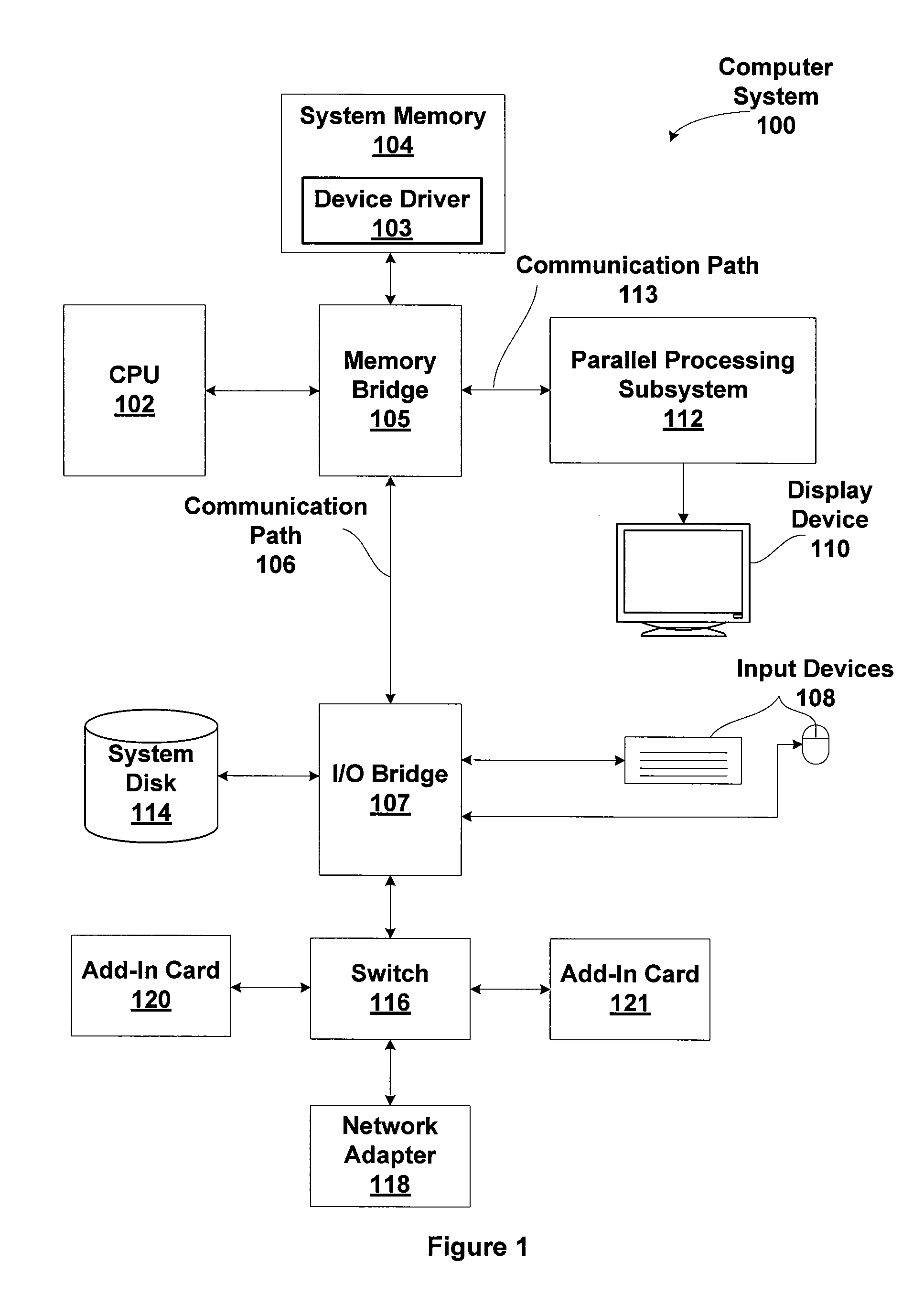
[0024]FIG. 1 is a block diagram illustrating a computer system 100 configured to implement one or more aspects of the present invention. Computer system 100 includes a central processing unit (CPU) 102 and a system memory 104 communicating via an interconnection path that may include a memory bridge 105. Memory bridge 105, which may be, e.g., a Northbridge chip, is connected via a bus or other communication path 106 (e.g., a HyperTransport link) to an I / O (input / output) bridge 107. I / O bridge 107, which may be, e.g., a Southbridge chip, receives user input from one or mor...


PUM


Abstract

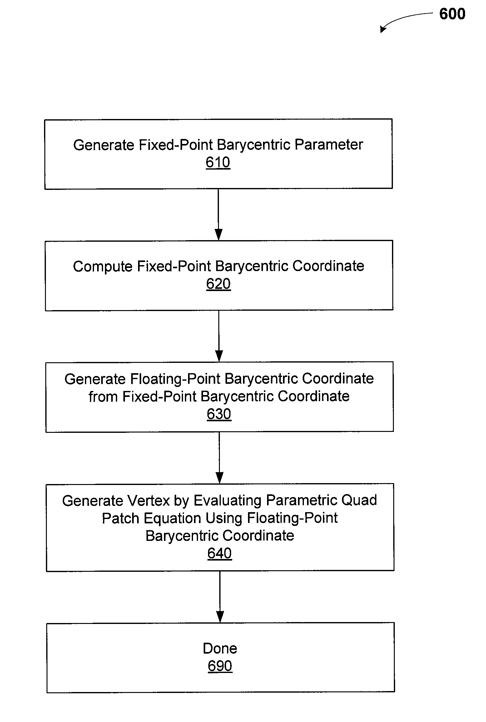
One embodiment of the present invention sets forth a technique for consistently evaluating geometric patches with shared boundaries using barycentric coordinates. A barycentric parameter is generated and represented using a fixed-point fraction. The barycentric parameter is then used to generate a fixed-point barycentric coordinate. The fixed-point barycentric coordinate is then converted to a floating-point representation for evaluating the geometric patches. Computing shared boundary splits using fixed-point fractions eliminates inconsistencies in associated barycentric coordinates due to round-off errors. Evaluating geometric patch equations using consistent barycentric coordinates facilitates precise, consistent computation of vertices along shared boundaries.

Description

BACKGROUND OF THE INVENTION[0001]1. Field of the Invention[0002]The present invention generally relates to geometric processing in graphics systems and more specifically to a system and method for symmetric parameterization of independently tessellated patches.[0003]2. Description of the Related Art[0004]Modern three-dimensional (3D) graphics systems are typically configured to generate one or more graphics images from one or more graphics scenes, with each graphics scene comprising one or more geometric models. The one or more graphics images are then displayed or stored for display later. Each geometric model may include geometric objects such as triangles, meshes, parametric patches, or other types of constructs useful in rendering a graphics scene. In many applications the meshes should not have any cracks or holes, and should not include any overlapping geometry. Certain types of high-level geometric objects, such as parametric patches, may be conveniently represented and manip...

Claims


Application Information

Patent Timeline
IPC IPC(8): G06T15/30G06T17/20
CPCG06T17/20
Inventor MORETON, HENRY PACKARD
Owner NVIDIA CORP
Learn More