AC energy generator

a generator and ac energy technology, applied in the direction of electric generator control, machine/engine, greenhouse gas reduction, etc., can solve the problems of known wind-powered electric generating systems, which have not utilized exhaust air from relatively low volume non-ventilation sources typical of air conditioner exhaus

Inactive Publication Date: 2013-10-22
NOVAK JOHN J
View PDF54 Cites 36 Cited by
  • Summary
  • Abstract
  • Description
  • Claims
  • Application Information

AI Technical Summary

Benefits of technology

[0013]The present invention structurally improves an existing wind powered generator by a novel rotating blade and design and mounting the generator in proximity to the air flowing into or out of the compressor housing. A novel shroud either circular to fit on top of a housing or curved to fit around a cylindrical housing is provided. The shroud is a grill that collects the circulating airflow and directs it to a plurality of wind turbines made of a plurality of closed end blades centrally twisted 180 degrees. As the airflow passes through the grill the novel blade structure insures that the turbine shaft is spun and electricity is virtually always generated when airflow is present. The novel blade design further serves to protect any person in the vicinity of the grill from harm.OBJECTS OF THE INVENTION
[0015]Another object of the present invention is to provide a new and improved air conditioner which utilizes an air flow energy converter and exchanger for indirectly reducing the total energy drawn from a commercial electricity supply grid to change the temperature of the air being conditioned thereby.

Problems solved by technology

Known wind powered electric generating systems, however, have not utilized exhaust air from relatively low volume non-ventilation sources typically found in air conditioner exhaust.

Method used


Image

  • AC energy generator
  • AC energy generator
  • AC energy generator

Examples


Embodiment Construction

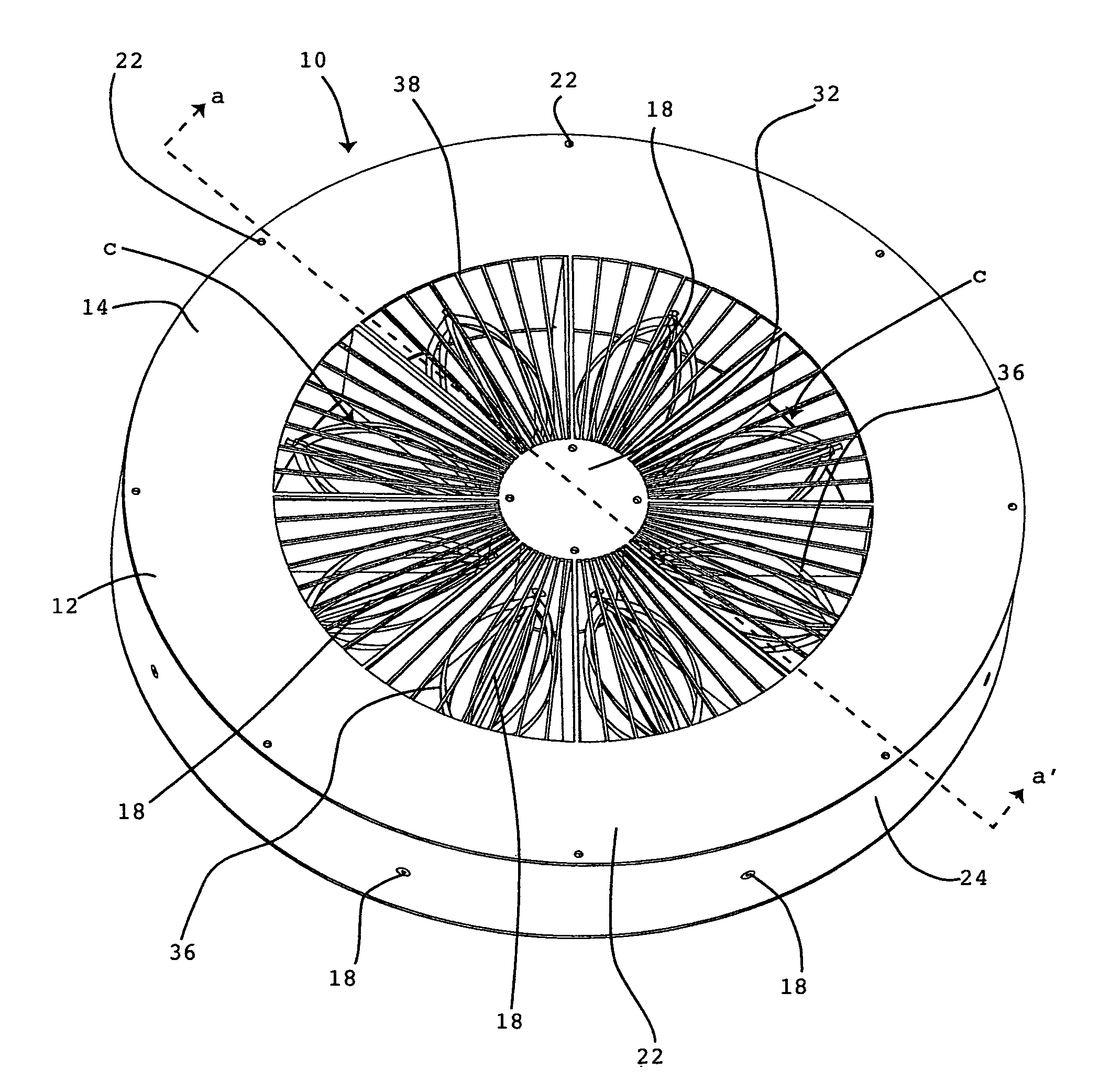
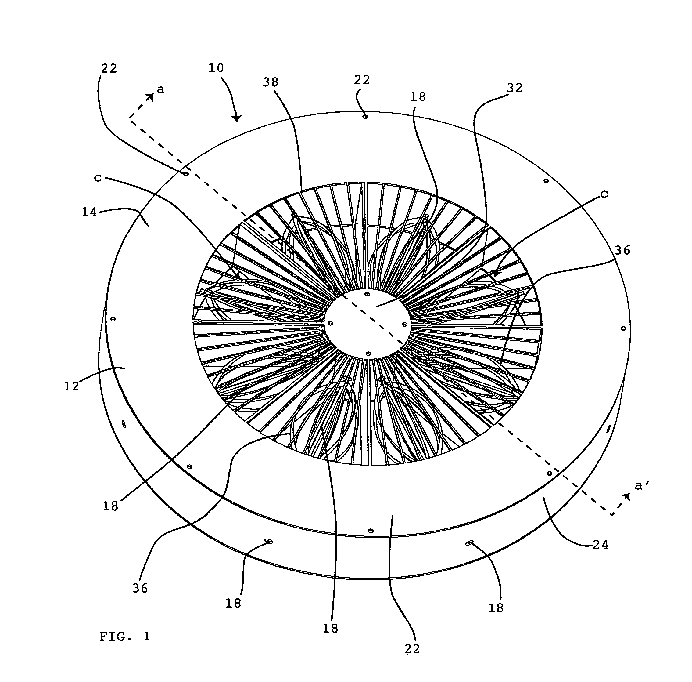
[0039]The primary purpose of the novel invention is to integrally decrease the amount of energy that an air-conditioned building consumes when an air conditioner or AC of specific design is operating. The specific AC is commonly referred to as a central AC compressor unit that is mounted outside the building on a support platform. The unit is cooled by air blown over the compressor as it heats up to cool it somewhat.

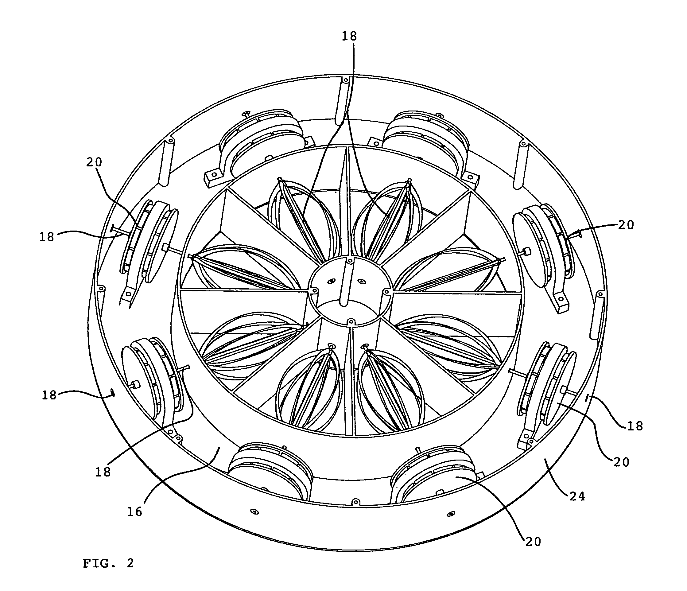
[0040]The novel invention is an add-on structure or disk 10 connected to an independent electrical box (not shown) containing the elements in the flow chart shown in FIG. 5 with the exception of the AC unit 116. The installed disk 10 is circular shaped, for example, and has therein a plurality of electromagnetic generators 20 powered by a plurality of closed circular blade turbines on shafts 18. The turbines each have a plurality of uniquely arranged closed circular blades 36 each connected to a shaft 18 that forms a part of the generator 20. Therefore, a turbine and a g...


PUM


Abstract

An electricity generator powered by air flowing from an air conditioner exhaust having a grill housing attached, the grill housing made of wind turbines connected to movable magnets freely movable clockwise or counter-clockwise to function whether the air flows in a first direction or opposite the first direction, thereby arranged to generate electromotive electricity as the turbines move, the turbines being oriented transverse to the air flow and a plurality of screws attaching the grill containing the wind turbines in a fixed transverse orientation relative to the air flow direction of the air conditioner exhaust wherein the wind turbine has a cage-like propeller with at least one flattened blade having a 180 degree twist located about mid-point and connected to a shaft, the shaft being connected to a generator and driving the generator creating electricity by moving conductors in a magnetic field. The grill holds the wind turbine so the blades are turned by exhaust air from the air conditioner and electricity is generated by moving conductors through alternating north and south magnetic fields.

Description

PRIORITY DATE CLAIMED[0001]The priority date claimed is May 20, 2010, the filing date assigned to this non-provisional application for a patent on this invention.BACKGROUND OF THE INVENTION[0002]1. Technical Field of the Invention[0003]The technical field of this invention concerns green energy or electricity generation from energy inherent during the movement of air from an exhaust of either a customary central or window air conditioner or heat pump.[0004]2. Description of the Related Art[0005]A need exists to increase the efficiency of machines used to cool and heat homes that are customarily referred to as air conditioners or heat pumps and consume alternating current electricity to power a compressor. The prior art developed to address this problem up to now has been from wind using a multiple blade like that of a fan mounted and turning on a shaft of a conductor, e.g. iron based stators, that move in a magnetic field to create electricity.[0006]Windmills, or wind turbines which...

Claims


Application Information

Patent Timeline
Patent Type & Authority Patents(United States)
IPC IPC(8): F01D15/10H02K7/18F02C6/00H02P9/04F03D9/00F03B13/00
CPCH02K7/183F03D9/00F05B2220/602F05B2220/604F05B2240/213F05B2240/40Y02E10/725Y02B30/52F03D9/11F03D9/25F03D80/70Y02E10/72Y02E70/30
Inventor NOVAK, JOHN J.
Owner NOVAK JOHN J
Why Eureka
Try Eureka