PWM heating system for eye shield

a heating system and eye shield technology, applied in underwater equipment, instruments, transportation and packaging, etc., can solve the problems of affecting vision, power source power that is easily carried on one's person, in order to sustain longer-term use, and has been limited, so as to achieve effective fogging prevention, efficient temperature management, and minimum attention

Active Publication Date: 2013-10-29
ABOMINABLE LABS LLC +1
View PDF21 Cites 25 Cited by
  • Summary
  • Abstract
  • Description
  • Claims
  • Application Information

AI Technical Summary

Benefits of technology

[0013]The device of this aspect of the invention provides a single-PWM, single heating region eye shield fog prevention device that enables efficient heating of the eye shield or lens so that battery life is maximized, since PWM can be preset to an output having a percentage ratio of on to off cycles that is tailored specifically to the particular goggle lens to which power is being applied.
[0020]The device of this aspect of the invention provides the ability of the CAM for efficient managing of the temperature of the eye shield lens at a temperature that is just above the dew point temperature to effectively prevent fogging with a minimum of attention by the user. This, in turn, allows power savings to enable longer battery life.
[0021]In accordance with another, fifth, aspect of the invention, there is provided an eye-shield condensation preventing system as previously described, whether a multiple-region, multiple-PWM embodiment, or a single-region, single-PWM embodiment, the device further comprising means for measuring ambient temperature and relative humidity and means for calculating dew point. The means for calculating dew point in this aspect of the invention is preferably operatively connected with the CAM (preferably further comprising microcomputer means) such that the CAM increases power to the electrical circuit when temperature within the space by the eye shield falls below the dew point temperature threshold and reduces power to the electrical circuit when temperature within the space defined by the eye shield climbs above the dew point temperature threshold. Thus the invention is capable of feeding a pulse to the resistive heating element, e.g., the film heating element, that is just enough to keep it at just above the dew point to effectively and automatically prevent fogging and to conserve battery life. The means for calculating dew point preferably comprises microcomputer means operatively connected with the temperature and relative humidity sensing means.
[0022]The eye-shield condensation preventing system of this aspect of the invention may further comprise a relative humidity sensor and a temperature sensor, each sensor located within the space defined by the eye shield. Such a system further comprises means, for example microcomputer means, operatively connected with the relative humidity and temperature sensor for periodically calculating dew point temperature. Further, the at least one pulse-width modulator is responsive to the means for periodically calculating dew point temperature to control the at least one heating element such that the at least one heating element is maintained at a temperature at above dew point to assure prevention of fogging over time.
[0026]Each of the eye shields disclosed herein are adapted for protecting a user's eyes from wind, debris, snow, rain, extreme temperatures and elements which could harm the eyes or otherwise impair vision. Each eye shield is also adapted to form and define at least a partial enclosure around and in front of the eyes. This enclosure warms up relative to conditions outside of the enclosure as a result of body heat transmitted into the space defined by the eye shield, and the enclosure also experiences higher relative humidity compared to outside conditions as a result of perspiration. When the temperature of the eye shield drops below the temperature within the eye shield at which dew, or condensation, would form on the inside of the eye shield, fogging of the eye shield occurs.

Problems solved by technology

Fogging that impairs vision is a common problem with such goggles, dive masks and eye-protecting shields.
A limitation of these devices has been that power source power that may be easily carried on one's person, for example on a head band or in a goggle or mask itself, in order to sustain longer-term use, has been limited.
Another problem with sport goggles which have employed electrical heating is that of uneven heating over the entire surface of the eye shield.
Even heating of this irregular shape has not been accomplished in the prior art.
Prior art devices have been susceptible to hot spots, and using such devices in limited battery-powered applications has unduly discharged the battery.
For example, where the terminals are on either side of the lens in a resistive wiring application, there have been problems with evenly heating the lens since the distance the wire has had to travel from one terminal to the other has been greater for those wires traveling over the bridge of the nose and down under the eyes than other wires that travel the shorter distance across a central portion of the lens.
To overcome fogging conditions enough power must be applied to overcome the fog in the areas with the greatest distance between the terminal connection points, causing the smaller areas to overheat, which in turn wastes power.
Thus, the problem has resulted in limited usefulness of heating of goggle eye-shields.
Because of the irregular shape of eye shields, these problems exist whether one is considering resistive wire applications or resistive-film applications.
Still another problem associated particularly with goggles and dive masks is the amount of space provided between the eye shield portion of the device and the user's face.
Further, where excess distance has been provided between the shield portion of the device and the user's eyes, the ability to incorporate corrective eye-shields into the goggle or mask eye shield itself has been prohibited.
The problem has been, increased distance between the user's eyes and the eye shield has improved anti-fogging capability in typical air-flow dependent anti-fog goggles, however, locating the eye shield at such a great distance from the user's eyes to facilitate anti-fogging has made corrective goggle eye-shields less effective for correcting vision.
Switching the power on to a goggle when you experience fog conditions, and then switching it off when a user suspects it is no longer needed, is not an efficient way to overcome fog in a goggle or other vision shield.
This is because while it is on, it is using full power and this is an inefficient use of battery resources.
Also, the user doesn't really know precisely when to turn it off, so at best the user is guessing when is the best time to turn it off.
Further, when a user is involved and concentrating on the activity at hand, it often is not convenient to have to turn on, or off, the power to the eye shield.
Manual switching of power to an eye shield doesn't allow the user to set an intermediate heat value that is sufficient to curtail fogging but which also conserves battery life.
Further, there are no known systems disclosed in the prior art for balanced heating of a film or other resistive element on an eye shield, such as goggles, glasses or sunglasses, which also provide variable control of a heating element on the eye shield.

Method used


Image

  • PWM heating system for eye shield
  • PWM heating system for eye shield
  • PWM heating system for eye shield

Examples


first embodiment

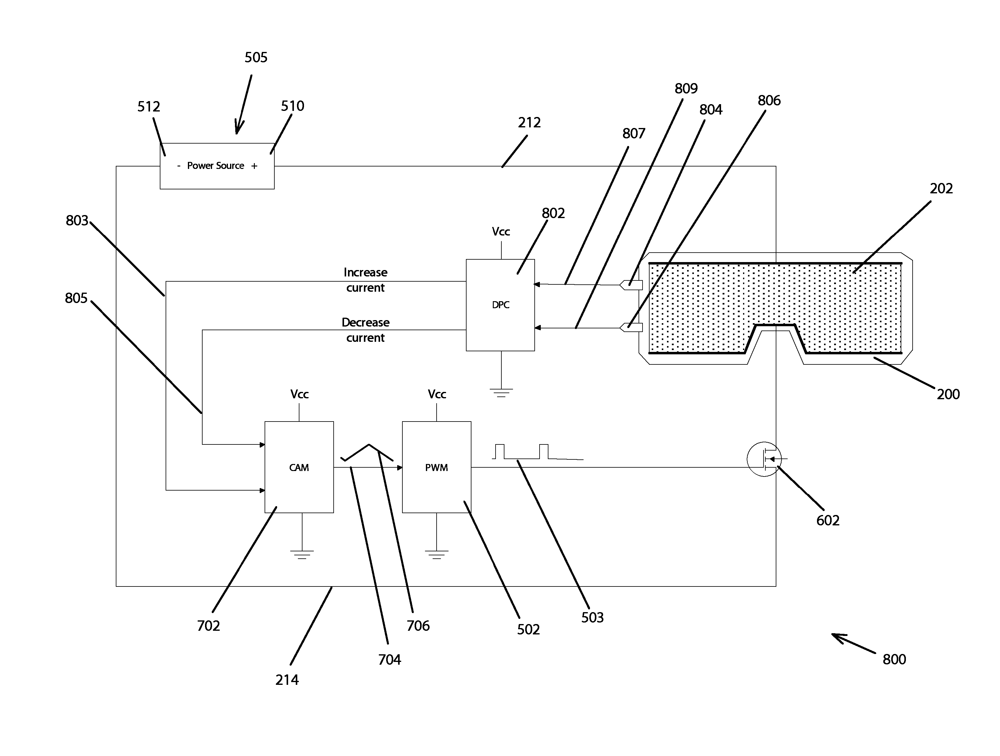
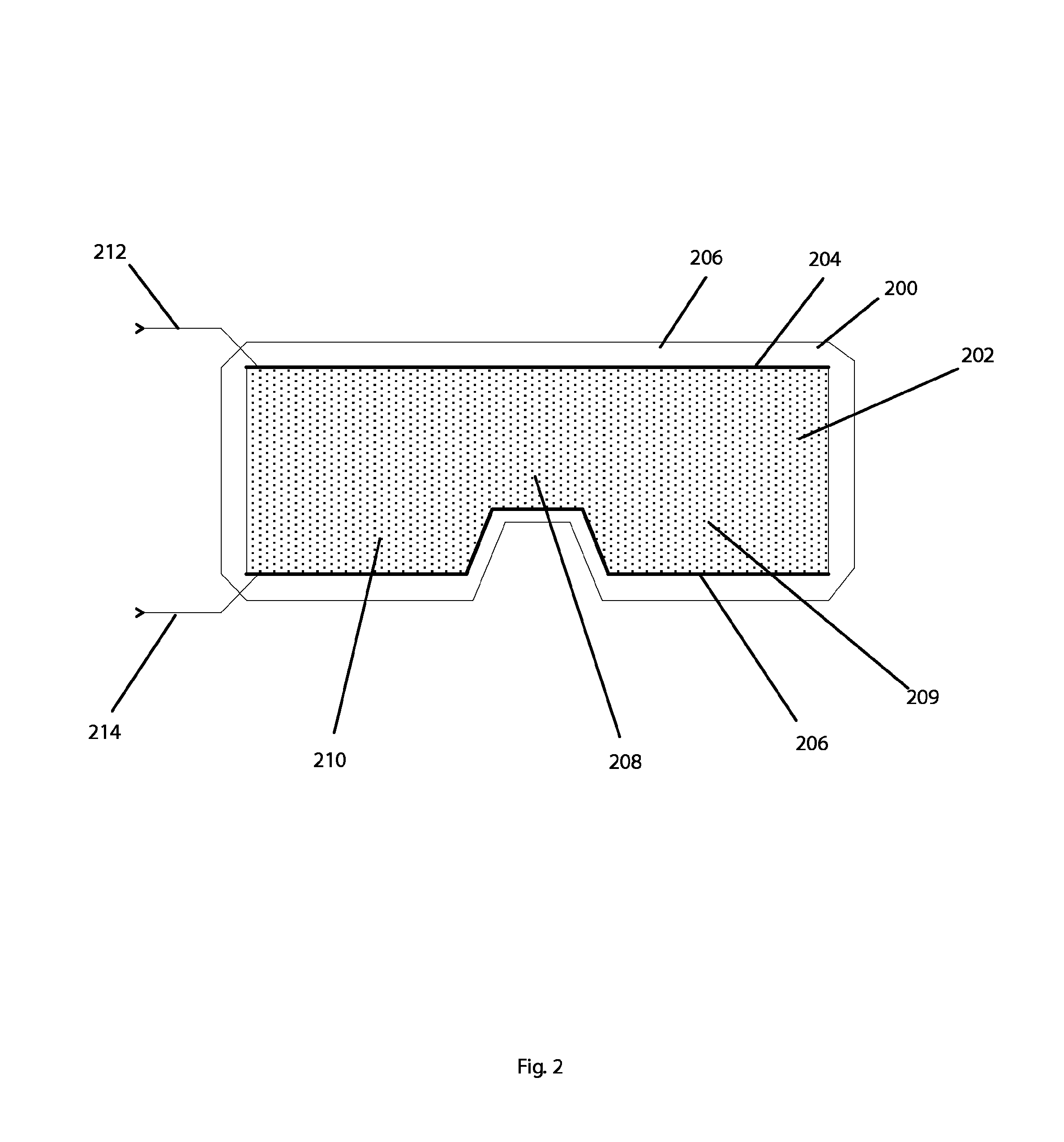
[0042]Referring to FIG. 2, there is provided in accordance with part of the invention an eye shield lens or protective eyewear 200 adapted for at least partially defining an enclosure around a user's eyes and having thereon a single-region resistive transparent conductive film heating member 202. Along an upper edge of the film heating member 202 there is a buss-bar heating element 204 interconnected with a power source (not shown) via a lead wire 212. The film heating member 202 may be comprised of indium-tin oxide (ITO) or other material designed in the form of a resistive element that generates heat when connected to an electrical circuit.

[0043]A lower buss-bar heating element 206 is provided along a lower edge of the film heating member 202 and which is interconnected with the power source via another lead wire 214. As is typical with many eye shields, such as in the case of winter sports goggles, the eye shield lens 200 is irregular shaped having two wider similarly shaped squa...

second embodiment

[0054]Referring to FIG. 4, an eye shield lens 400 is provided in accordance with the invention. The eye shield 400 is adapted for at least partially defining an enclosure in front of the user's eyes and has deposited thereon a plurality (24 are shown in FIG. 4) of resistive heating film zones or regions 402 A-X. It will be appreciated that the resistive heating film may be divided into larger or smaller regions than shown without departing from the true scope and spirit of the invention. Each resistive film region 402 A-X is connected to a terminal of a power source via lead wires and discrete buss-bars 404a-x. A single buss-bar 406, located along a lower edge of each resistive film region 402 A-X interconnects each of the lower ends of film regions to a ground terminal of the power source.

[0055]The resistive film regions of the fog prevention system of the present invention are preferably deposited on the inner surface of an eye shield 200, 300, 400 with a process known as ion sput...


PUM


Abstract

Eye-shield condensation preventing system comprising an eye shield adapted for protecting a user's eyes and adapted for defining at least a partially enclosed space between the user's eyes and the eye shield, a power source, a pulse-width modulator preferably comprised of a microcomputer, switching means, preferably comprised of a MOSFET device, that is responsive to the pulse-width modulator, a preferably indium-tin-oxide (ITO) heating element on the eye shield, and a circuit interconnecting the power source, the pulse-width modulator, the switching means and the heating element for controlling heating of the eye shield. In one embodiment the eye shield is divided into a plurality of heating regions. A current adjustment means, sensors, and optionally user-selectable profiles are employed to allow heating adjustment or automated anti-fog capability and variable condition adaptability of the invention.

Description

FIELD OF INVENTION[0001]This invention relates to heating of an eye shield to prevent fogging of a protective eye shield, and more particularly to electronic power source-powered heating of a resistive element attached to an eye shield for preventing fogging of such as would be useful in de-fogging a goggle, a dive mask or other portable transparent eye-protecting shield.BACKGROUND OF THE INVENTION[0002]It is often desirable to use sport goggles, dive masks and other highly portable transparent eye-protecting shields in environments involving conditions which contribute to condensation build-up on the eye shield and where even momentary impairment of vision by fogging would be problematic. When the temperature of such an eye shield has dropped below a dew-point temperature, i.e., the atmospheric temperature below which water droplets begin to condense and dew can form, fogging has occurred.[0003]A common characteristic of such portable eye-protecting shields is the fact that they ar...

Claims


Application Information

Patent Timeline
Patent Type & Authority Patents(United States)
IPC IPC(8): A41F9/00
CPCA42B3/245B63C11/28B63C11/12G02C11/08A61F9/028A61F9/022H05B1/023H05B3/84H05B2203/013
Inventor CORNELIUS, JACK C.
Owner ABOMINABLE LABS LLC
Why Eureka
Try Eureka