
Self sensing component interface system

a component and interface technology, applied in the field of self-sensing component interface systems, can solve the problems of extended and expensive downtime of the entire associated process line, failure of products produced, and failure of process, so as to maximize the “uptime” of the process line, reduce costs, and optimize process performance

Active Publication Date: 2013-10-29
ROCKWELL AUTOMATION TECH
View PDF4 Cites 179 Cited by
  • Summary
  • Abstract
  • Description
  • Claims
  • Application Information

AI Technical Summary

Benefits of technology

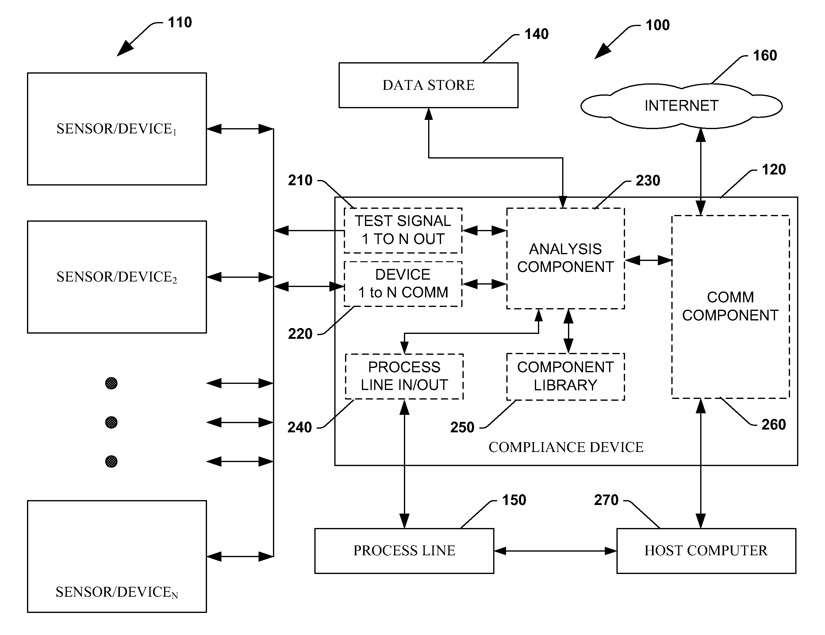
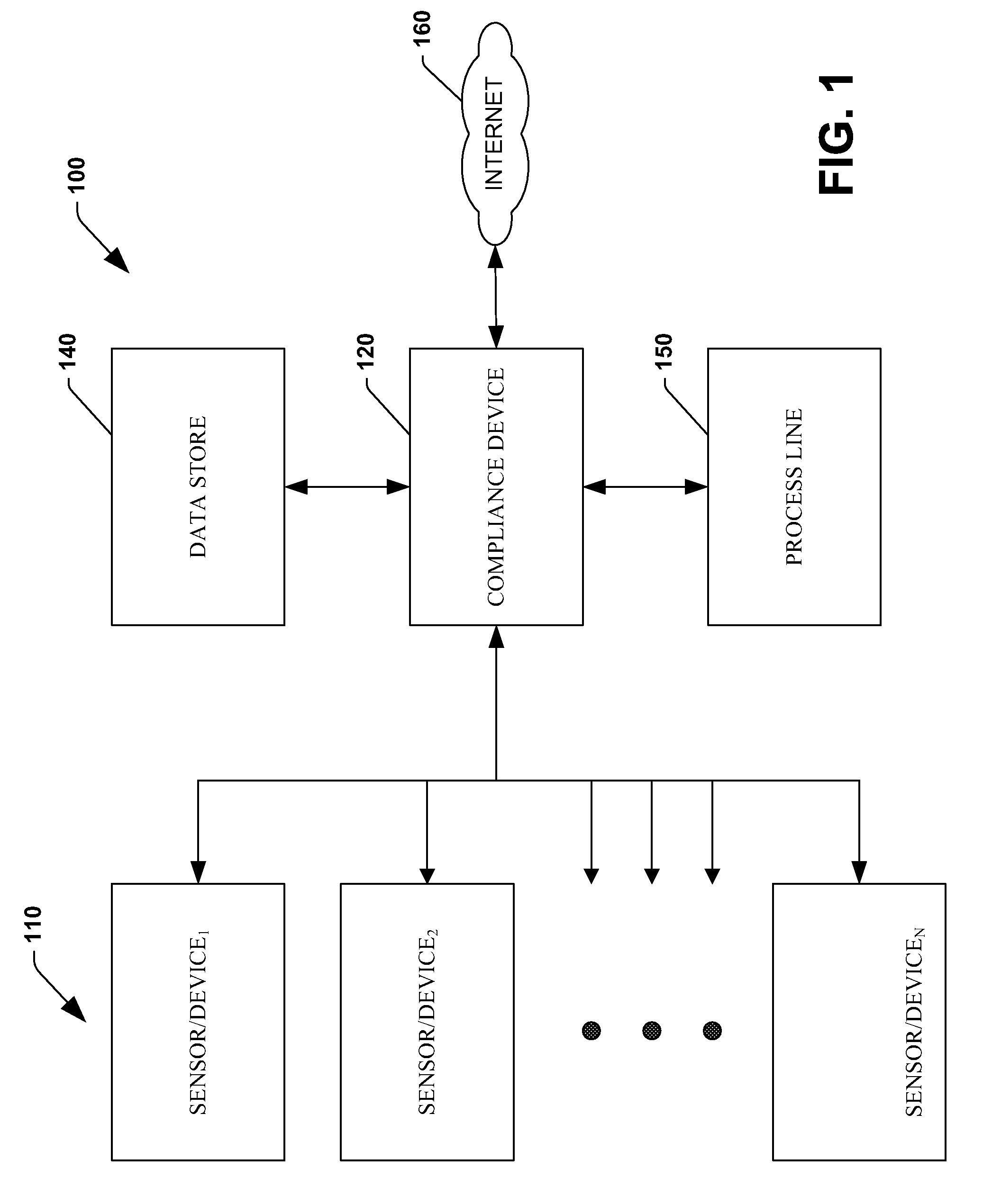
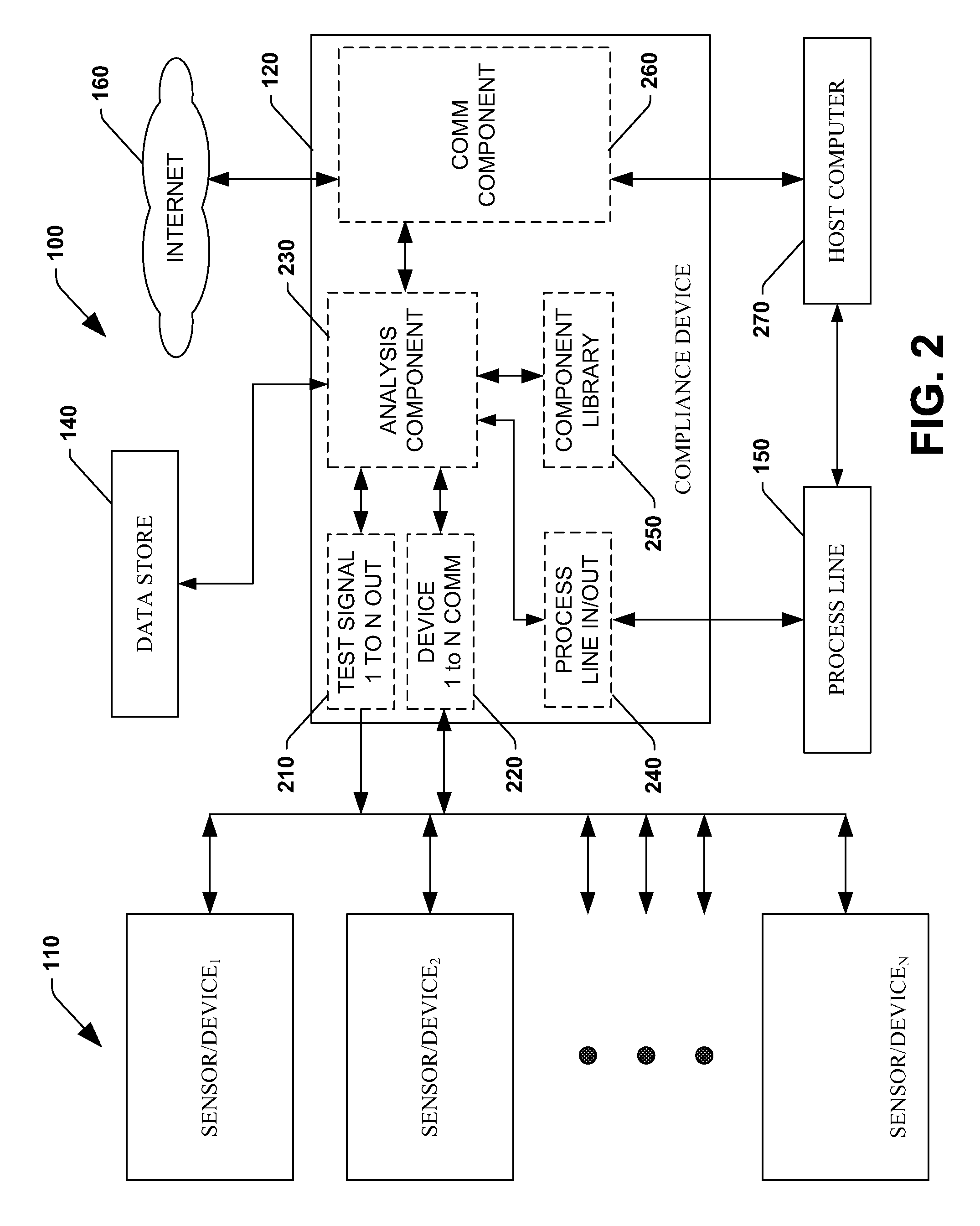
[0011]The invention provides control systems and methodologies for controlling a process having one or more sensors or other devices associated with a process line, which provide for optimized process performance according to one or more performance criteria, such as efficiency, component life expectancy, lower cost or better performing sensors from differing manufacturers meeting minimum sensor or device specifications (e.g., compliant sensors or devices), maximizing process line “uptime” by monitoring sensor performance for real-time or predictive analysis degradations, providing datum for analysis of optimum replacement windows, or the like. Additionally, the compliance of a sensor or device can be more easily assessed by analyzing data or handshakes ascertained from a sensor or device associated with a process line. More particularly, the subject invention provides for employing machine diagnostic and / or prognostic information in connection with optimizing an overall business operation. Thus, the present invention abstracts sensor or device data so that it can be employed in connection with optimizing overall business operations as compared to many conventional systems that employ sensor or device data solely in connection with machine maintenance.

Problems solved by technology

Further, such sensors frequently monitor the human interface components of process lines and may control process line interlocks (e.g., they may interrupt or halt an active production line, or prevent the startup of a production line, based on an operator or worker's actions, or process line or environmental conditions, in relation to sensors associated directly or indirectly with the process line).
Sensors or devices that fail to meet these compliance requirements (e.g., noncompliant sensors or devices) may result in failure of a process line to start-up where a noncompliant sensor or device is connected to a process line interlock, cause damage to the process line either by causing the process line to run outside of acceptable parameters or by direct damage to the process line (e.g., the noncompliant device causes a power spike on a system bus damaging other electrical components, the noncompliant device causes a repetitive stress injury to a process line worker interacting with the device, etc.), cause failures of products produced on or associated with a process line associated with the noncompliant device (e.g., a noncompliant temperature sensor on a chemical process line may change the reaction temperature by providing erroneous temperature readings resulting in no damage to the process line but resulting in a chemical product that is dangerous or otherwise outside of acceptable product parameters, etc.), other unacceptable conditions, or combinations thereof among others.
For example, a break press workstation may be combined with a pressure sensor to ensure that a worker is in the proper position to operate the break press on the production line, as well as with several other sensors monitoring the position of work pieces entering and exiting the break press to ensure that the work pieces are properly positioned for operation of the break press, whereby the failure of any sensor, use of an incompatible sensor, or worse, the intentional bypassing of a sensor, may result in a failure of the process (e.g., damaging work pieces, the break press itself, the operator or bystanders, and may result in extended and expensive downtime of the entire associated process line).
While the operating specifications for the sensor system components may provide for component device selection to achieve one or more system operational maxima (e.g., temperatures, caustic chemical resistance, etc.), other performance metrics (e.g., efficiency, cost, lifetime, MTBF, sensor degradation, etc.) for the components and / or the system of which they form a part, are not typically optimal.
For example, even where a sensor may be replaced with an identical sensor upon failure, the replacement may not be optimal where an improved replacement sensor has become available.
The cost of replacing a sensor that impacts a production line is not just the cost of the sensor itself, rather it must include the cost of lost production and exposure to risk for production line workers.
Repeated replacement of sensors with substandard components, inoperative components, or improper components, is likely inefficient and costly.
These issues may be magnified where single vendor sensor system component selection is not desirable from a cost or availability standpoint.
Purchasing sensor system components from discrete vendors may reduce costs to the production line owner but correspondingly may increase costs for determining which vendor's product has failed, designing a metric system for comparing components from separate vendors, and management costs of replacements components.
Moreover, typically, the specification for such machines or components thereof is performed at an isolated level or level of granularity such that higher-level aspects of a business or industrial concern are overlooked.
If after the analysis is complete, the device or system is not compliant it is not permitted to be integrated with the system.

Method used


Image

  • Self sensing component interface system
  • Self sensing component interface system
  • Self sensing component interface system

Examples


Embodiment Construction

[0024]The subject innovation is now described with reference to the drawings, wherein like reference numerals are used to refer to like elements throughout. In the following description, for purposes of explanation, numerous specific details are set forth in order to provide a thorough understanding of the claimed subject matter. It may be evident, however, that such matter can be practiced without these specific details. In other instances, well-known structures and devices are shown in block diagram form in order to facilitate describing the invention.

[0025]As used in this application, the terms “component,”“handler,”“model,”“system,” and the like are also intended to refer to a computer-related entity, either hardware, a combination of hardware and software, software, or software in execution, in addition to electro mechanical units. For example, a component may be, but is not limited to being, a process running on a processor, a processor, an object, an executable, a thread of e...


PUM


Abstract

The subject innovation provides for systems and methods to optimize control systems for networked industrial sensors or devices and methods for self sensing, communicating with, monitoring of, controlling and optimizing utilization of networked industrial sensors and related control systems primarily in an industrial automation environment. The invention provides self-sensing and communication with sensors, and integration of control methods and strategies with decision support and logistics systems, to optimize specifically defined operational and performance objectives.

Description

TECHNICAL FIELD[0001]The present invention relates to the art of networked industrial sensors and control systems (e.g., networked industrial process-line interlock systems and components thereof) and more particularly to control systems and methods for self-sensing, communicating with, monitoring of, controlling and optimizing utilization of networked industrial sensors and related control systems primarily in an industrial automation environment. The invention provides self-sensing and / or communication with sensors, and integration of control methods and strategies with decision support and logistics systems, to optimize specifically defined operational and performance objectives.BACKGROUND OF THE INVENTION[0002]The global economy has forced many businesses to operate and conduct business in an ever increasingly efficient manner due to increased competition. Accordingly, inefficiencies that were once tolerated by corporations, due to a prior parochial nature of customers and suppl...

Claims


Application Information

Patent Timeline
Patent Type & Authority Patents(United States)
IPC IPC(8): G06Q10/00
CPCG06Q10/06G06Q10/08G06Q50/04G06Q50/28Y02P90/30Y02P90/80
Inventor GURU, ARUN K.YEGOROV, ALEKSEYSCHMIDT, ROBERT HARRIS
Owner ROCKWELL AUTOMATION TECH
Learn More