Wheel suspension for a motor vehicle

a technology for motor vehicles and suspensions, applied in the direction of motor vehicle propulsion, mechanical energy handling, transportation and packaging, etc., can solve the problem of significant increase in the induced voltage generated in the generator, and achieve the effect of efficient induced voltage during driving operation

Active Publication Date: 2013-11-05
AUDI AG
View PDF19 Cites 13 Cited by
  • Summary
  • Abstract
  • Description
  • Claims
  • Application Information

AI Technical Summary

Benefits of technology

[0007]It is an object of the invention to provide a wheel suspension with an electric vibration damper with a generator constructed to efficiently induce a voltage during driving operation.

Problems solved by technology

This significantly increases the induced voltage generated in the generator.

Method used


Image

  • Wheel suspension for a motor vehicle
  • Wheel suspension for a motor vehicle
  • Wheel suspension for a motor vehicle

Examples


Embodiment Construction

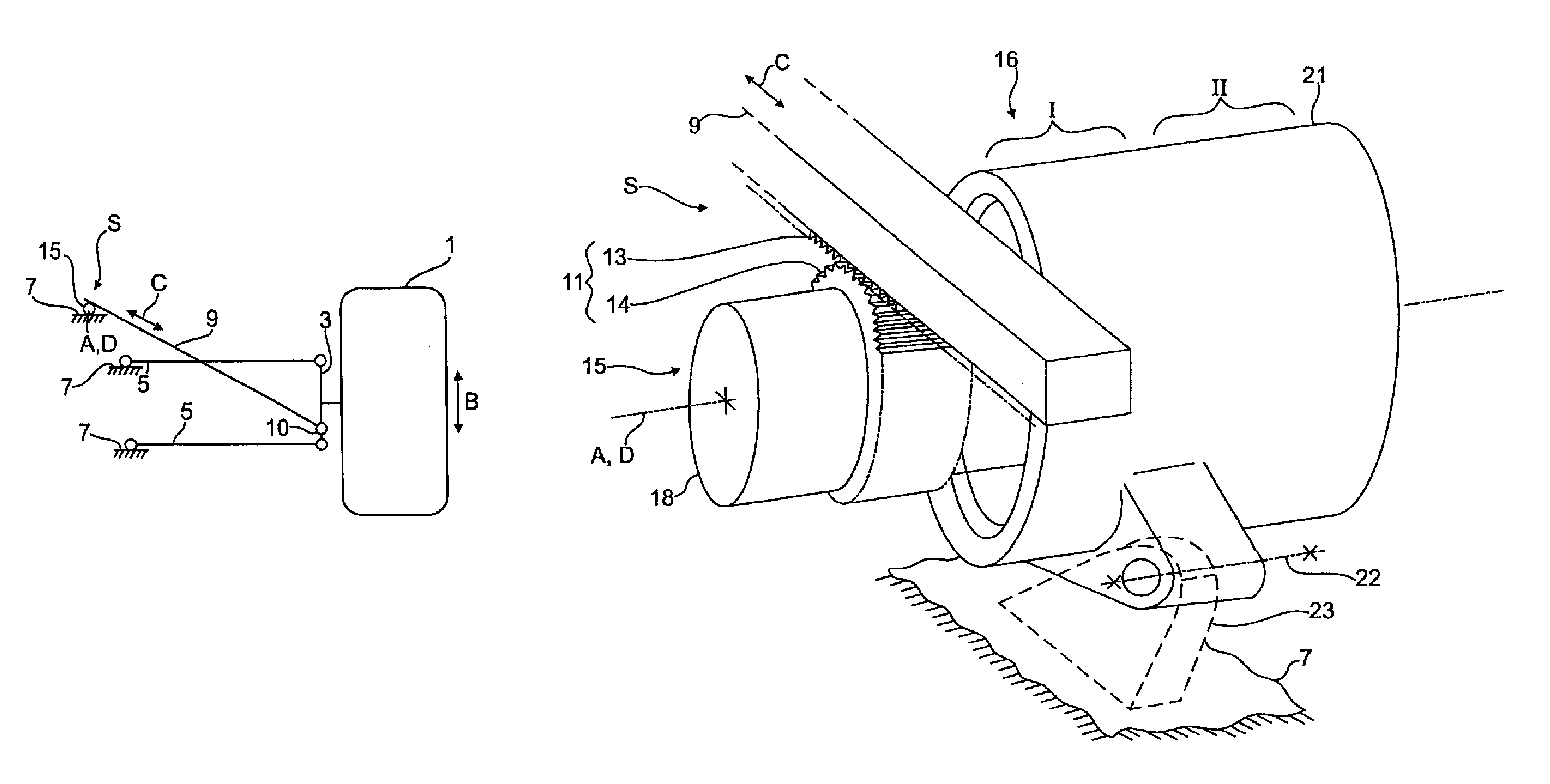
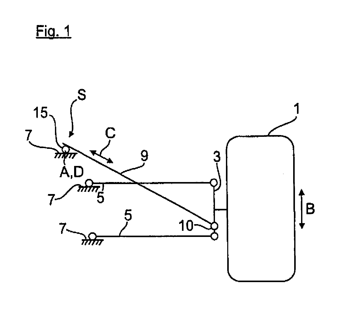
[0023]FIG. 1 shows the wheel suspension of a vehicle wheel of a motor vehicle 1. The vehicle wheel 1 is rotatably mounted on a wheel carrier 3. The wheel carrier 3 is articulated on the vehicle body 7 via transverse control arms 5. In addition, the wheel carrier 3 is connected with the vehicle body 7 at a pivot point S via a semi-trailing control arm 9, particularly for pivoting about a pivot axis D. As further shown in the FIG. 1, the semi-trailing control arm 9 is coupled to the wheel carrier 3 via a pivot bearing 10. This construction enables a smooth transfer of the translatory up and down movements B toward the electric vibration damper 16.

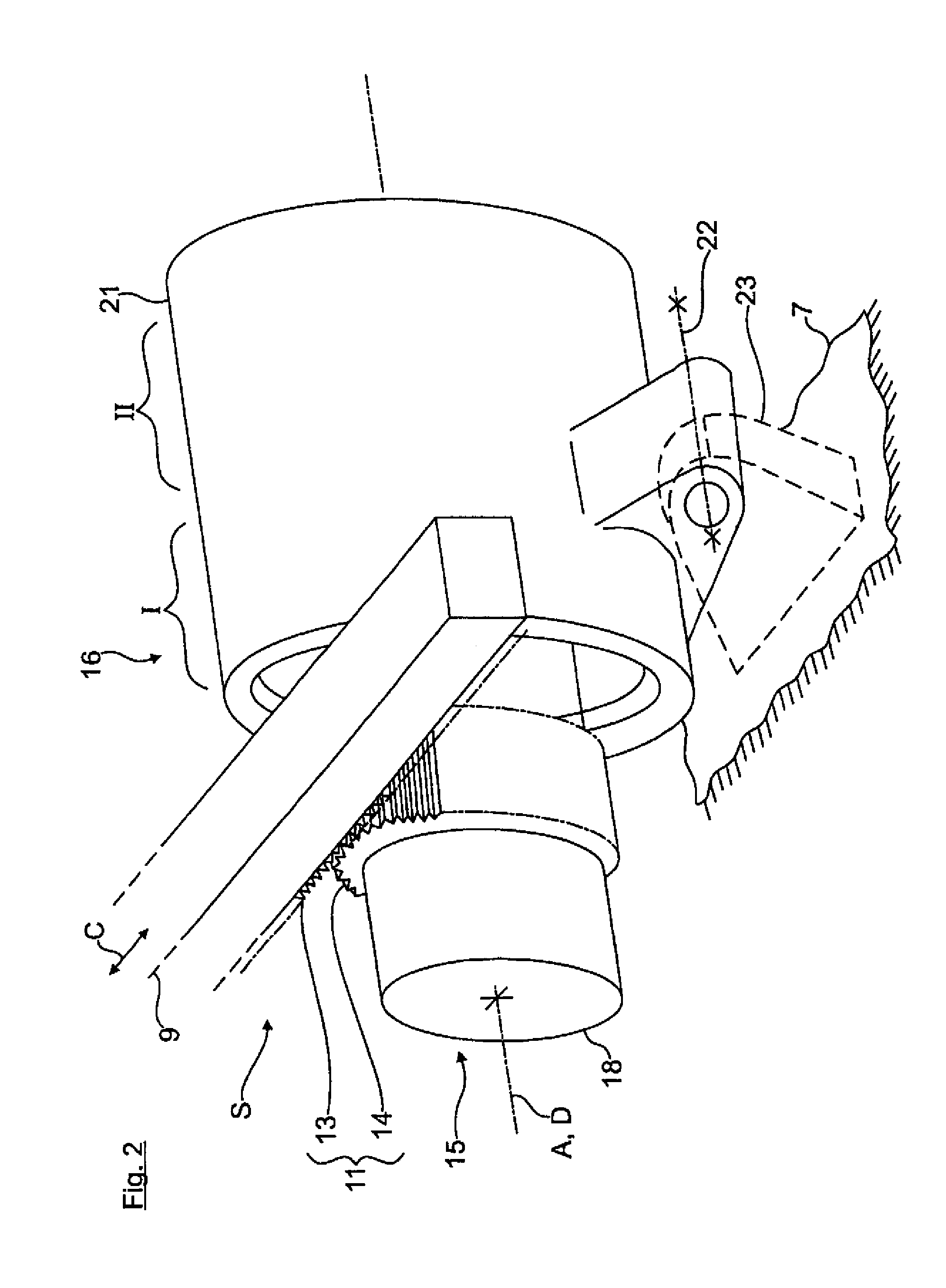
[0024]FIG. 2 shows on an enlarged scale the pivot point S between the semi-trailing control arm 9 and the vehicle body 7. The semi-trailing control arm 9 is articulated via a rack-and-pinion gear 11, as shown in FIG. 2. The rack-and-pinion gear 11 has as a cooperating gear member a rack portion 13 which is integrally formed on the end of the ...


PUM


Abstract

A wheel suspension for a motor vehicle includes an electric vibration damper which is affixed to the vehicle body and which has a generator that can be driven by translational wheel movements of the vehicle wheel in order to generate an induced voltage. The stator and the rotor of the generator are interconnected via at least one gear stage, wherein a gear element of the gear stage is a drive gear wheel of a rack-and-pinion drive that is drivingly connected to a wheel carrier of the wheel suspension, with the wheel carrier following the wheel movements.

Description

CROSS-REFERENCES TO RELATED APPLICATIONS[0001]This application is the U.S. National Stage of International Application No. PCT / EP2011 / 003626, filed Jul. 20, 2011, which designated the United States and has been published as International Publication No. WO 2012 / 025176 and which claims the priority of German Patent Application, Serial No. 10 2010 035 088.5, filed Aug. 21, 2010, pursuant to 35 U.S.C. 119(a)-(d).BACKGROUND OF THE INVENTION[0002]The invention relates to a wheel suspension for a motor vehicle.[0003]The wheel suspension of a motor vehicle may have an electric shock absorber, which attenuates the operational vehicle vibrations. The electric shock absorber may include a generator which converts the vibration energy into electrical energy that can be supplied via corresponding power electronics to the onboard electrical system of the vehicle.[0004]DE 101 15 858 A1 discloses an electric vibration damper of this type with a generator driven by the operational up and down movem...

Claims


Application Information

Patent Timeline
Patent Type & Authority Patents(United States)
IPC IPC(8): B60G13/14B60G17/06
CPCB60G13/14B60G17/0157H02K7/116H02K35/00H02K7/1853B60G2200/144B60G2202/22B60G2202/42B60G2204/4192B60G2300/60F16F15/03
Inventor WILLEMS, MARCO
Owner AUDI AG
Why Eureka
Try Eureka