Moulding device

a moulding device and moulding technology, applied in the field of moulding equipment, can solve the problems of limited control of the process, inbuilt stress and quality loss of the product, and the limit of the maximum flow path and material wall thickness that can be achieved, so as to improve the quality of the part, improve the flow control, and prolong the flow path

Active Publication Date: 2013-11-05
TACX ROEREND & ONROEREND GOED BV
View PDF14 Cites 0 Cited by
  • Summary
  • Abstract
  • Description
  • Claims
  • Application Information

AI Technical Summary

Benefits of technology

[0040]An advantage is that the design allows for longer flow paths of the molten material to be achieved and for better control of the flow.
[0041]As a result internal part stresses are eliminated, better part quality is achieved with longer usage time, better chemical and physical resistance with excellent surface finish.
[0042]A further advantage is that cooling times are significantly reduced with the result that the cycle times are much reduced.
[0043]This then has a direct impact on the production cost and the parts can be produced in high volumes at lower cost and besides this the energy cost is reduced as well with the consequent reduction in greenhouse gases as a result.
[0044]Another advantage is that the minimum amount of machine clamp force can be used as is necessary according to the design, meaning that special heavy expensive equipment construction and frequent resetting of the machine parameters are avoided.

Problems solved by technology

With this conventional technique and its resulting high pressure there are limitations on the maximum flow paths and material wall thicknesses that can be achieved.
This results in turn in in-built stresses and quality loss in the product.
Such a technique is referred to as (Injection) Compression Moulding which has the main drawback of being a process that has limited control, in contrast to the above referred to conventional technique of injection moulding.
A known disadvantage of the latter method is that the material flows in an uncontrolled manner into the mould, which is a relatively large open space.
Furthermore the plastic cools at the contact areas, in an uncontrolled manner, between which the hotter high flow material then gets pressed.
The resultant formation of such jetting effects is an important drawback in particular with amorphous materials especially when the visual aspect of the product is important.
Uncontrolled crystallisation also results in the formation of undesirable cold fronts in the material that can lead to weaknesses and quality issues in the end product.
A known disadvantage is that the moulded parts are relatively small and thick walled and that the part design is limited to just very simple cylindrical parts.
A well know drawback of this process is that it can only be used to produce parts that are essentially flat or slightly bent such as for example optical lenses for sunglasses, safety glasses and so forth and which preferably have a wall thickness of 3.6 to 3.5 mm.
A known drawback of such a process is that only products with a simple geometry can be produced given that the moveable core can only close onto the opposite form half in a perpendicular way in order to have the effect of lowering the machine's closing force, by reducing the surface area of the mould half
A further drawback of this method is that flow lines and stresses are produced in and around the cavities that are formed following the withdrawal of the moveable cores, which are then filled in a second injection step.
These flow lines and stress lines cannot be removed despite various secondary treatments, such as thermal annealing.
In summary one can say that all the above mentioned processes are more machine process linked meaning that it is not possible to have a closed loop process control of the system without taking into account the material properties.

Method used


Image

  • Moulding device
  • Moulding device

Examples


Embodiment Construction

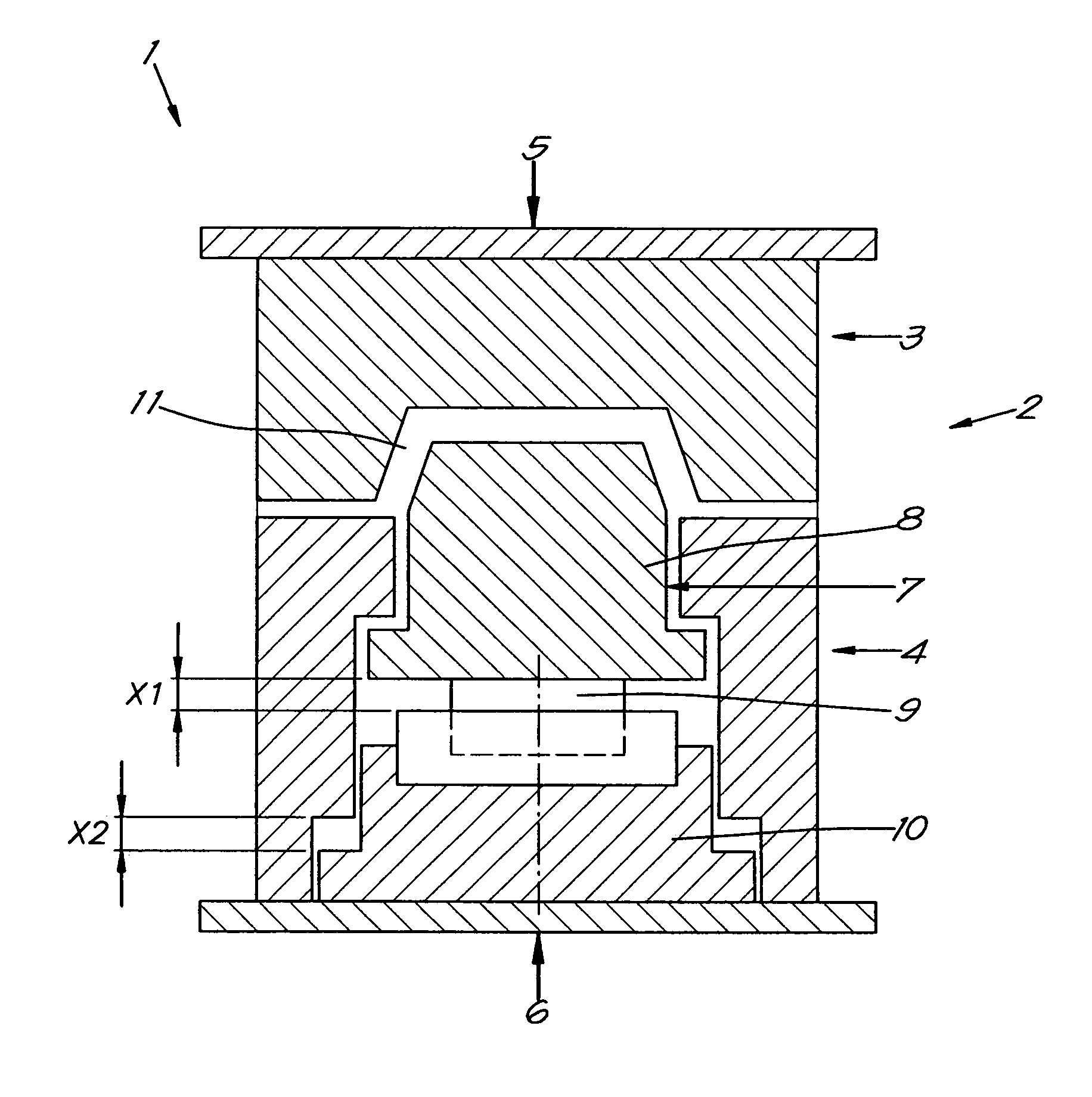
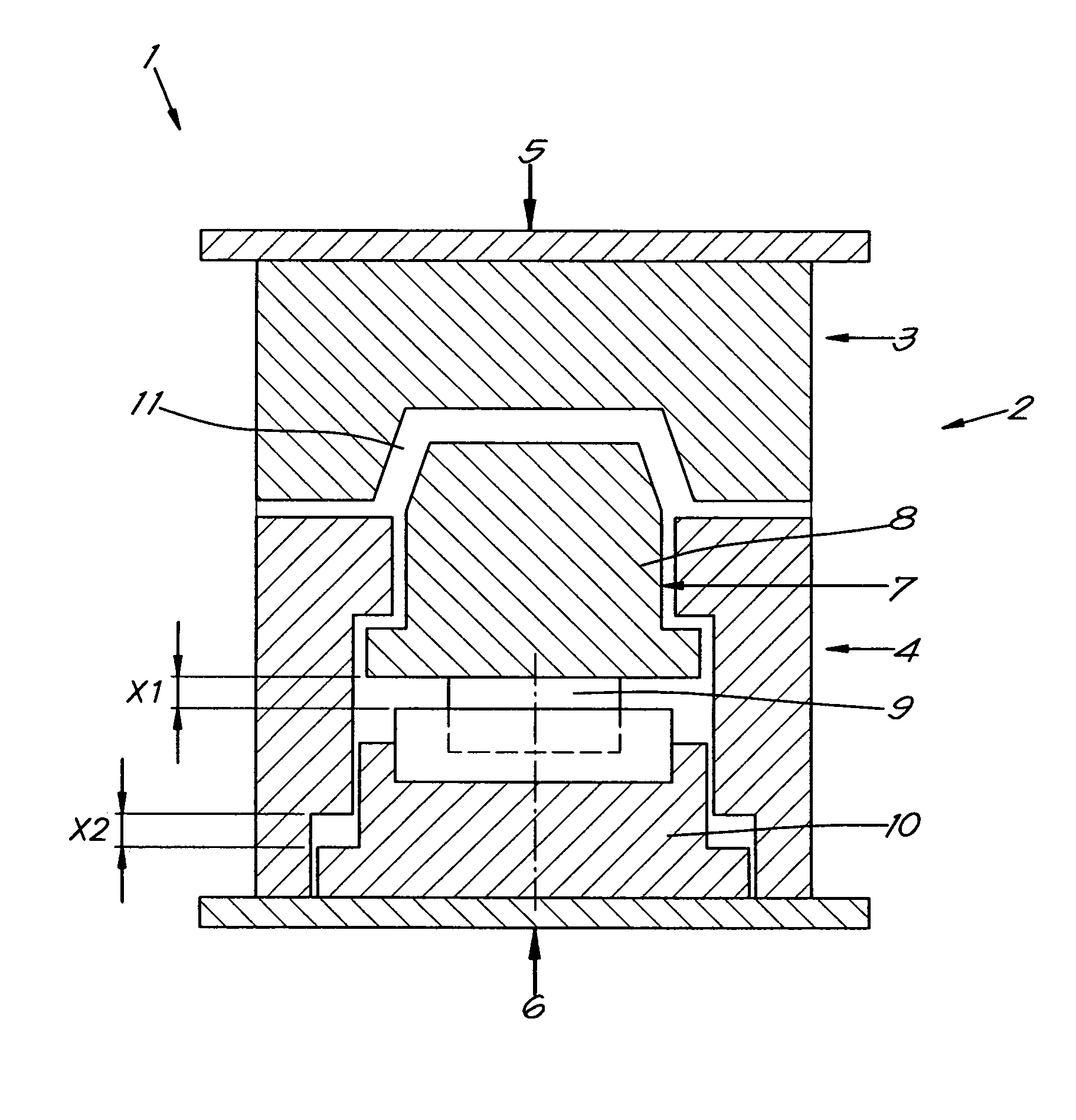
[0052]FIG. 1 shows a cross section of the equipment 1, consisting of a mould 2 which in turn consists of two part forms or mould halves 3 and 4, which are held closed together by a closing force indicated by the arrows 5 and 6.

[0053]In the mould half 4 is housed the moveable mould part 7.

[0054]The moveable mould part 7 is in turn composed of a moveable core 8, which can reach into the other mould half 3, and an adjustable positioning device that is simply shown here by a hydraulic cylinder 9, whereby the core 8 can be moved up and back over a variable distance X1 or just kept in position.

[0055]A second adjustable positioning device, here simply shown by an hydraulic cylinder 10, can function separately or in combination with the cylinder 9, to position the moveable core 8 back to its initial or starting position via controlled movement over the distance X2.

[0056]Between the moveable core 8 and the mould half 3 a cavity 11 is defined, the form of which is equal to that of the final p...


PUM

PropertyMeasurementUnit
thicknessaaaaaaaaaa
pressureaaaaaaaaaa
sizeaaaaaaaaaa

Abstract

Moulding equipment for the production of plastic parts via the injection of a molten thermoplastic resin, chiefly consisting of a mould (2) which consists of at least two mould halves (3,4), which when closed together produce a cavity (11) and a core (8), wherein at least one mould half or mould part (3 and / or 4) contains at least one moveable mould part (7) with the necessary system to control the movement of the mould part or parts (7) using the active control of the cavity (11) pressure.

Description

CROSS-REFERENCE TO RELATED APPLICATIONS[0001]This application is the National Stage of International Application No. PCT / IB2008 / 002406, filed Sep. 15, 2008, the contents of which is incorporated by reference herein.FIELD OF THE INVENTION[0002]The current invention refers to a moulding equipment.[0003]More specifically the invention refers to equipment for injection moulding plastics.BACKGROUND OF THE INVENTION[0004]The invention can also be applied to the injection of other materials, for example metals such as aluminium or brass and hence the invention is not necessarily limited to just the injection of plastics only.[0005]The invention equally can be applied in the case that the moulding equipment needs to be modified.[0006]With conventional injection moulding of plastics, molten plastic is injected, under relatively high pressure, into a clamped closed mould cavity.[0007]With this system of injecting into a closed mould cavity the pressure builds up inside the mould and is depend...

Claims


Application Information

Patent Timeline
Patent Type & Authority Patents(United States)
IPC IPC(8): B29C45/56
CPCB29C45/561B29C2045/563B29C2945/76006B29C2945/76257
Inventor VAN DEN BOER, DANNY
Owner TACX ROEREND & ONROEREND GOED BV
Why Eureka
Try Eureka