Method for production of a solid oxide fuel cell (SOFC)

a fuel cell and solid oxide technology, applied in the direction of manufacturing tools, sustainable manufacturing/processing, final product manufacturing, etc., can solve the problems of fuel cell premature aging, frequent problem of fitting on the inside of the electrolyte body, etc., and achieve the effect of simple manner

Inactive Publication Date: 2013-11-05
ROBERT BOSCH GMBH
View PDF6 Cites 23 Cited by
  • Summary
  • Abstract
  • Description
  • Claims
  • Application Information

AI Technical Summary

Benefits of technology

[0004]The object of the present invention is therefore to overcome the disadvantages mentioned above relating to the production of a solid oxide fuel cell, and to provide a method for producing an electrolyte body, as well as the electrodes and corresponding interconnector layers which are required on the inside and / or outside of the electrolyte body, in a simple manner.
[0009]The injection molding core may be formed with a conical external contour, such that a first end with a large diameter and a second end with a small diameter of the injection molding core are formed, wherein the second end with the small diameter constitutes the side of the electrolyte body which forms the holding end of the tubular electrolyte body on a base body. If the interconnector material and / or the internal electrode are / is now applied to the injection molding core by means of a printing process, in particular by means of a web-fed printing process or a screen printing process, then the application can be carried out such that a cylindrical overall body is produced after application of the interconnector material and the material of the internal electrode. This results in an area of the interconnector material which has a greater wall thickness, with this area being used to subsequently make electrical contact with the internal electrode, because the highest current density occurs at the contact end of the interconnector material. This allows the thickness of the interconnector material to be matched to the current density over the length of the electrolyte body.
[0012]According to a further advantageous embodiment, the injection molding core may have grooves into which the interconnector material is introduced, in order to form an interconnector layer which has a structure, preferably a web structure or a grid structure. By way of example, the interconnector material can be introduced into the grooves in the injection mold by a wiper. In consequence, the interconnector forms a matrix structure on the electrode, in order not to cover it completely. The number of grooves can advantageously be increased over the length of the injection molding core in one direction in the structure, in order to form a larger line cross section in the direction in which contact will later be made with the interconnector, in order to carry the greater current density.

Problems solved by technology

In addition to the mounting of the electrodes on the finished electrolyte body, so-called interconnectors are applied flat to the electrodes in order to make contact with them, in which case fitting on the inside of the electrolyte body frequently leads to problems.
The chromium-oxide layer which is formed during operation of the fuel cell in this case has a negative effect on the cathode material, and can lead to premature aging of the fuel cell.
Because the electrolyte bodies are very thin, there are major problems associated with fitting ceramic interconnectors to the inner wall of the electrolyte body.
The problem results in particular from the thin walls since, for example, the electrolyte body preferably has a wall thickness of about 200 μm, in which case the porous anode on the inside of the electrolyte body must be coated with a ceramic interconnector layer.

Method used


Image

  • Method for production of a solid oxide fuel cell (SOFC)
  • Method for production of a solid oxide fuel cell (SOFC)
  • Method for production of a solid oxide fuel cell (SOFC)

Examples


Embodiment Construction

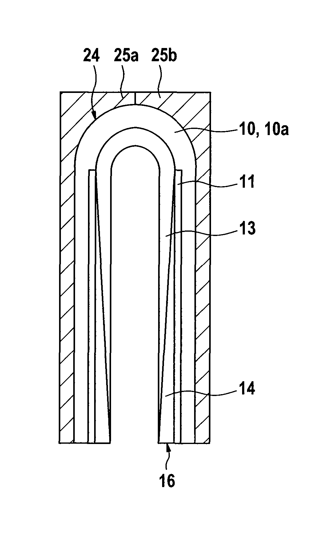
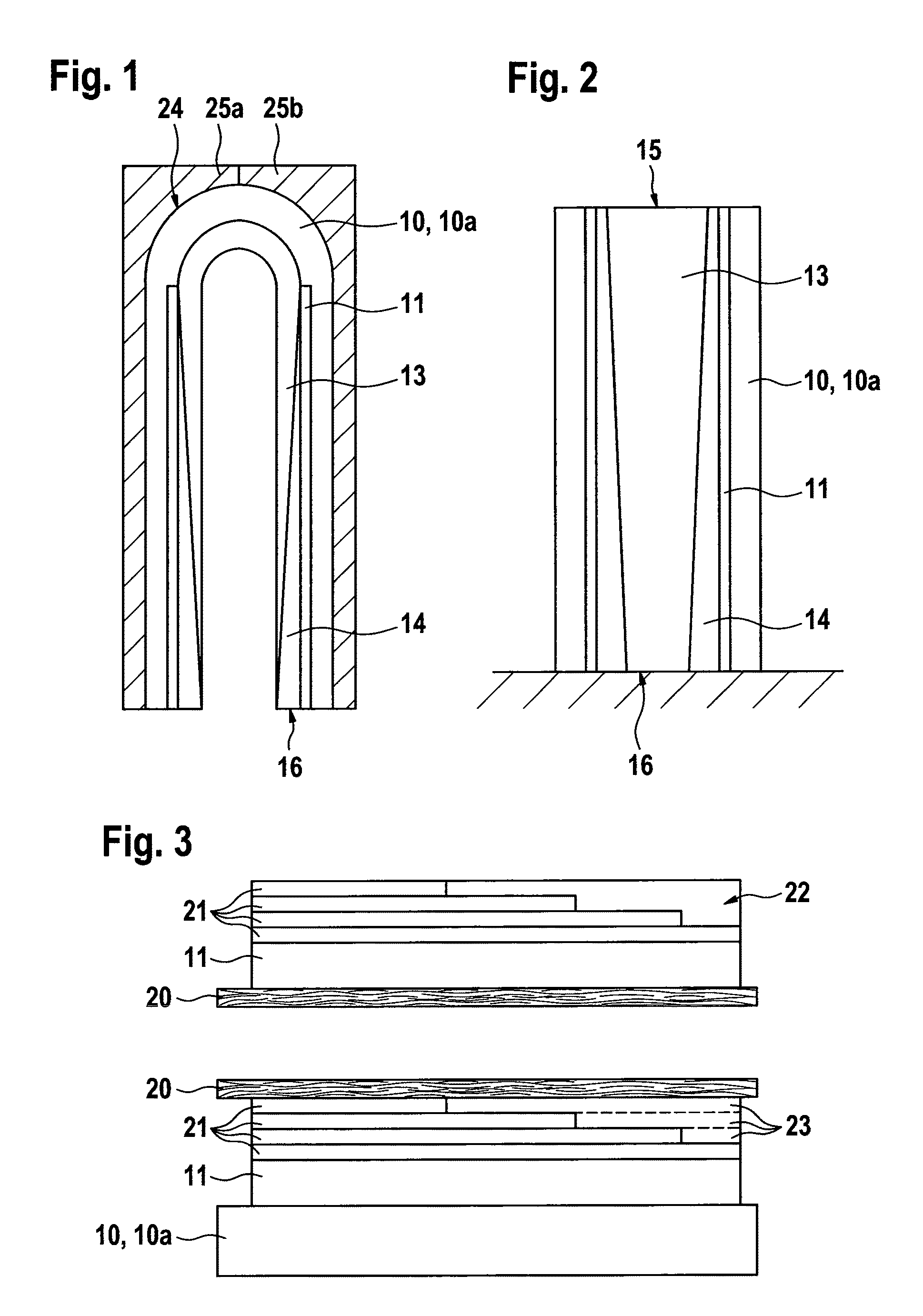
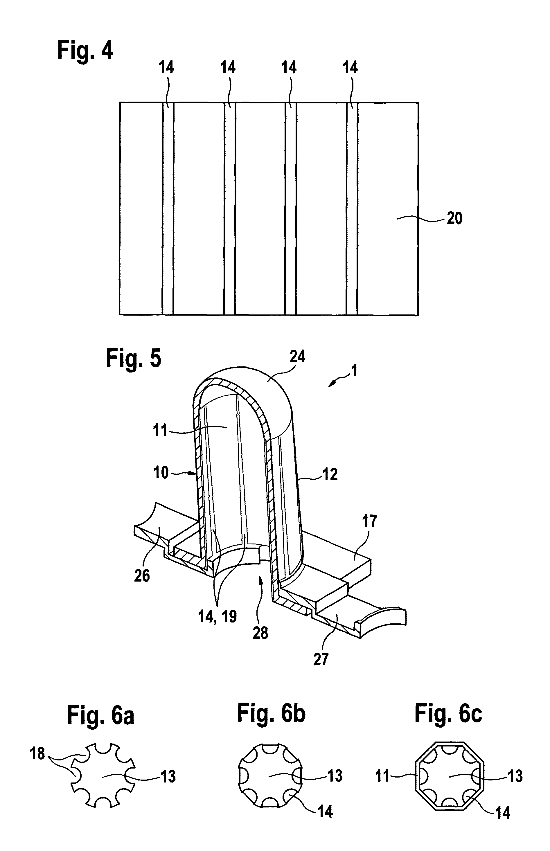
[0024]FIG. 1 shows a schematic view of one exemplary embodiment of the method for production of a solid oxide fuel cell1, as is illustrated in perspective form in FIG. 5. First of all, FIG. 1 shows a cross section through an injection mold, which has a first mold element 25a and a second mold element 25b. The mold elements 25a and 25b can move with respect to one another, and can be moved apart from one another in order to remove an injection-molded electrolyte body 10 from the mold. The electrolyte body 10 is in the form of an electrolyte body that is closed at the ends, and therefore has a cap 24. According to one possible embodiment for production of the electrolyte body 10, this may be in the form of a single part, such that the tubular, cylindrical section of the electrolyte body 10 can be produced by injection of an electrolyte compound 10a into the injection mold, in which case the cap 24 can also be produced by the electrolyte compound 10a itself in the injection mold. On th...


PUM

PropertyMeasurementUnit
thicknessaaaaaaaaaa
thicknessaaaaaaaaaa
diameteraaaaaaaaaa

Abstract

A method for production of a solid oxide fuel cell (SOFC) (1), having an electrolyte body (10) with a tubular structure, wherein at least one internal electrode (11) and one external electrode (12) are applied to the tubular electrolyte body, with the method having at least the following steps: provision of an injection molding core (13) on which at least one interconnector material (14) and the internal electrode (11) are mounted, arrangement of the injection molding core (13) in an injection mold (25a, 25b), injection molding of an electrolyte compound (10a) in order to form the electrolyte body (10), and removal of the injection molding core (13) in the form of a casting process with a lost core.

Description

BACKGROUND OF THE INVENTION[0001]The present invention relates to a method for production of a solid oxide fuel cell (SOFC) having an electrolyte body in tubular form, wherein at least one internal electrode and one external electrode are applied to the electrolyte body.[0002]Solid oxide fuel cells (SOFC) with a ceramic electrolyte body form a high-temperature variant of fuel cells. They are operated at 600° C. to 1000° C., and in the process provide very high electrical efficiencies of up to about 50%. In principle, solid oxide fuel cells are subdivided into two main variants: one variant is formed by a tubular shape of the electrolyte body which, according to a further variant, can be bounded, by a flat, planar form. In this case, it is necessary to fit the internal and external electrodes to the wall of the electrolyte body during the method for production of a solid oxide fuel cell based on the tubular variant. For this purpose, it is known for the electrode which is arranged on...

Claims


Application Information

Patent Timeline
Patent Type & Authority Patents(United States)
IPC IPC(8): H01M8/12B29C45/14
CPCB28B1/24B28B7/342H01M8/124H01M8/1213H01M8/004Y02E60/521Y02E60/525H01M2008/1293Y02P70/50Y02E60/50
Inventor MAUS, HARALDGLANZ, UWESATET, RAPHAELLEOEHLER, GUDRUNSCHWEGLER, LEONOREHAGEMANN, BENJAMINBLUTHARD, ALEXANDERHIRTH, ERHARD
Owner ROBERT BOSCH GMBH
Why Eureka
Try Eureka