
Luminaire illumination system and method

a technology of illumination system and illumination source, applied in the field of led illumination, can solve the problems of not providing a source of bright illumination, unable to meet the needs of lighting, and bare wood can be difficult to keep lit, so as to reduce the thermal gradient, improve lighting quality, and reduce the thermal signature of lighting sources.

Active Publication Date: 2013-11-05
MERCURY MISSION SYST LLC
View PDF180 Cites 8 Cited by
  • Summary
  • Abstract
  • Description
  • Claims
  • Application Information

AI Technical Summary

Benefits of technology

The patent text describes various ways to reduce the thermal signature of a lighting source and improve the quality of lighting. One way to do this is by distributing the heat generated by the light source over a larger area to decrease the thermal gradient between the heat sink and the ambient area. Another way is to provide a spatial distribution of light flux within a region of interest that is preferably highly uniform. Additionally, the patent describes improving the output angular characteristics of an LED source by applying a diffuser to its front surface. The patent also suggests reducing or eliminating a source's dazzling effect by providing asynchronous modulation of the light intensity across multiple lights. Additionally, the patent suggests controlling the spectral characteristics of LEDs to create desired environmental simulation by adding spectral control or color components. This can be done to mimic diurnal lighting changes and improve human wake-up habits in artificial lighting conditions.

Problems solved by technology

However, bare wood can be difficult to keep lit and does not provide a source of bright illumination.
While this can be aesthetically pleasing to some, it can also be viewed as inefficient by others.
Point sources can present a source non-dazzling illumination.
With this approach, an observer sees a large number of point sources (like a star field in the sky), but each such elementary source is rather weak.
However, a large reflector is used and the dust and environmental pollution can introduce unwanted scattering.
However, the usual architecture lighting does not require uniform distribution in certain direction, so proposed designs are rather overcomplicated.
Unfortunately, collimation can present a solution that is too restrictive for obtaining a uniform distribution when a source array is used to light the environment.

Method used


Image

  • Luminaire illumination system and method
  • Luminaire illumination system and method
  • Luminaire illumination system and method

Examples


fourth embodiment

[0148]In FIG. 13, the fourth embodiment is shown, where a number of LEDs, 108a, 108b, and 108c are mounted around a central rod 107, illuminating sideways ray illuminated from surface 113. The metallic reflector is a quasi-parabola of rotation around axis 115. Quasi-parabolas' axis 114 crosses the LED surface 113 (in a particular case, a quasi-parabola becomes off-axial parabola of rotation). In the illustrated example, the LED power supply 110 is mounted into an Edison connector 106. While the embodiments illustrated in FIGS. 10, 11, 12 and 14 utilize a material with a refractive index different from that of air to achieve reflection and refraction in accordance with Snell's law, the embodiment of FIG. 13 uses air surrounded by the metallic reflector 109. Also, the illustrated example includes a protective cover 116 such as glass, polycarbonate or other protective material.

first embodiment

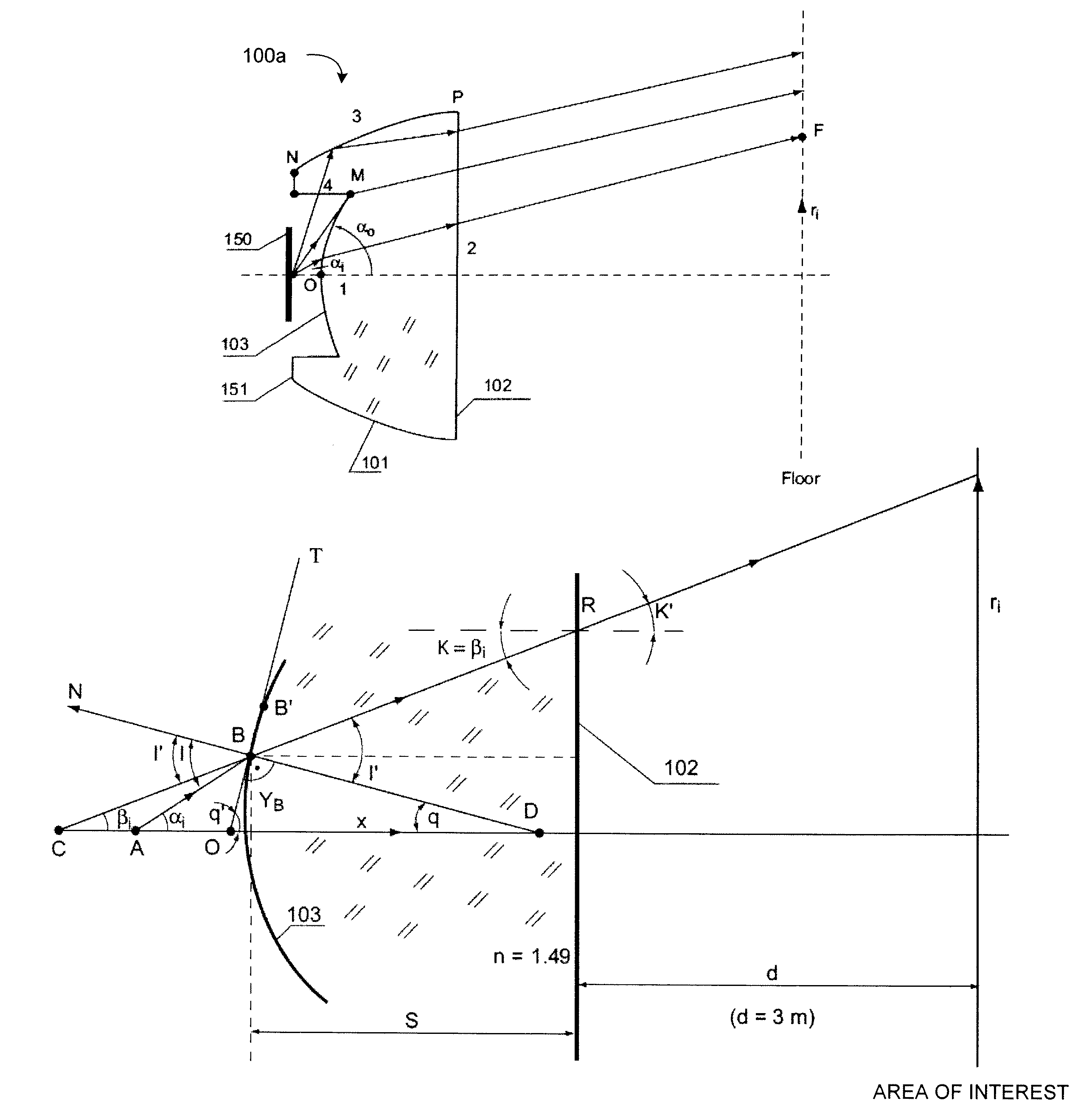
[0149]FIG. 14 is a diagram illustrating still another example embodiment of an LED luminaire. Referring now to FIG. 14, this embodiment is similar to the first embodiment as shown in FIG. 10. However, in the example illustrated in FIG. 14, part of surface 101 near the source, is covered by a reflective coating 117 such as a metallic layer. The inclusion of a metallic coating 117 can facilitate internal reflection. For example, a metallic coating 117 can provide regular Fresnel reflection from the metallic interface instead of relying solely on total internal reflection as a result of the critical angle between the transformer 100e. With a reflective metallic coating 117, internal reflection is achieved without the same limitations imposed by Snell's law. Accordingly, reflective coatings 117 can be used to allow a more compact design. With the example illustrated in FIG. 14, the reflective coating 117 is provided near the light source as this is the area of the beam transformer 100e ...


PUM


Abstract

A method of constructing a non-imaging beam transformer includes reducing a tailored illumination function from a predetermined light source to a source point response illumination function; calculating a plurality of transformation pairs for the predetermined light source, the transformation pairs identifying the radii of illumination of the light source at given source output angles; determining a desired lighting profile for light output at a region of interest to be illuminated by the beam transformer; determining a surface profile of a surface of the beam transformer such that for given output angles of the light source, the transformation pairs at those output angles are satisfied to correspond to the desired lighting profile; and constructing the beam transformer having the surface profile determined based on the transformation pairs. The method can include characterizing a specific angular output distribution of a light source to calculate the transformation pairs.

Description

REFERENCE TO RELATED APPLICATIONS[0001]This application claims priority to U.S. Provisional Patent Application No. 61 / 155,460, filed Feb. 25, 2009, the contents of which is incorporated herein by reference in its entirety.TECHNICAL FIELD CROSS[0002]The present invention relates generally to lighting and lighting systems and methods, and more particularly, some embodiments relate to LED illumination for a variety of environments.DESCRIPTION OF THE RELATED ART[0003]Fire was arguably one of early mankind's most important discoveries. Indeed, early men and women relied heavily on fire, not only for warmth and for cooking, but also as a source of light. Thus, fire was one of the first sources of artificial illumination, or illumination from sources other than the sun. The earliest form of artificial illumination, then, was merely burning wood as a source of lighting. However, bare wood can be difficult to keep lit and does not provide a source of bright illumination. Accordingly, artific...

Claims


Application Information

Patent Timeline
Patent Type & Authority Patents(United States)
IPC IPC(8): G01B9/02
CPCF21V13/04G02B27/0927G02B19/0028F21S8/068F21V5/005F21V5/008F21V5/045F21V7/0091F21Y2101/02F21K9/137F21K9/233F21Y2115/10
Inventor JANNSON, TOMASZAGUROK, ILYAFORRESTER, THOMASPRADHAN, RANJITSHIH, MIN-YI
Owner MERCURY MISSION SYST LLC
Learn More