System for connecting motor drives

a technology for connecting systems and motor drives, applied in the direction of multiple conductor connectors, connection contact material, coupling device connections, etc., can solve the problems of short circuit conditions, large installation time, and large time-consuming for wiring electronic components, and achieve quick coupling or uncoupling, facilitate quick connection of electronic components to each other, and facilitate quick connection of electronic devices to each other

Active Publication Date: 2013-11-19
ROCKWELL AUTOMATION TECH
View PDF10 Cites 8 Cited by
  • Summary
  • Abstract
  • Description
  • Claims
  • Application Information

AI Technical Summary

Benefits of technology

[0007]In accordance with another aspect of the invention, the insulating cover may include a pair of opposing side walls that extend over a pair of opposing side walls of the bus bar module. The clip side walls may slidingly engage the insulating cover side walls so that the clip can move longitudinally with respect to the bus bar module while being transversely guided upon the bus bar module. This may allow conductors within the bus bar connector system to be covered quickly during assembly.
[0008]In accordance with another aspect of the invention, the bus bar connector system includes first and second bus bar modules. The first and second bus bar modules may be connected to each other at a splice joint. The splice joint may include a conductive receptacle that holds respective ends of the first and second bus bar modules, so that their blades or exposed conductive surfaces contact the conductive receptacle so as to electrically connect the first and second bus bar modules to each other. The clip may cover the splice joint so that the covered surfaces of the bus bars of the first and second bus bar modules and the clip define a continuously covered length of the combination of the first and second bus bar modules and splice joint. This may allow bus bars to be quickly coupled to or uncoupled from each other which may facilitate connecting electronic components to each other while providing a connector system that has its conductive surfaces substantially covered with insulating materials.
[0009]In accordance with another aspect of the invention, the conductive receptacle may be provided in a plug housing of an adapter plug. The conductive receptacle may be provided at a first end of the adapter plug and a second end of the adapter plug may be operably coupled to a connector that is fixed to a printed circuit board of an electronic device. This may facilitate quickly connecting electronic devices to each other.
[0010]In accordance with another aspect of the invention, the clip may be slidably mounted to the first bus bar module and may be slidable over the plug housing and upon the second bus bar module, so that the clip covers the entire splice joint and overlaps portions of the first and second bus bar modules. A lock may be provided that prevents sliding movement of the clip with respect to the splice joint. The lock may include a lock projection and a cooperating lock receptacle on the clip and at least one of the adapter plug and first and second bus bar modules, which can engage each other to secure the clip in place when it covers the splice joint. This may allow the clip to remain in a position in which it covers the splice joint that connects bus bars to each other so that conductive materials of the splice joint remain unexposed or substantially covered with insulating materials.
[0011]In accordance with another aspect of the invention, each bus bar module may include a pair of bus bars that are transversely spaced and electrically insulated from each other. Each adapter plug may include a pair of connective receptacles that are transversely spaced from and insulated with respect to each other. This may facilitate simultaneously connecting positive and negative bus bars to electronic components which may simplify connecting such electronic components to each other by allowing multiple connections to be made in a single installation step.
[0012]In accordance with another aspect of the invention, the bus bar connector system may be implemented within an industrial control system and may connect multiple motor drives to each other. First, second, and third adapter plugs may be connected to first, second, and third motor drives of the industrial control system. A pair of bus bar modules may be longitudinally aligned with each other so that outer ends of the bus bar modules are connected to the first and third adapter plugs. Inner or inwardly positioned ends of the bus bar modules may be connected to each other at a spliced joint defined at the second adapter plug and a clip may extend over the splice joint. The bus bar connector system may include the same number of adapter plugs as the number of motor drives that are being connected and may include one fewer bus bar module than the number of motor drives and adapter plugs. This may facilitate connecting multiple motor drives to each other in a tool-less manner.

Problems solved by technology

The inventors have recognized that wiring electronic components such as, for example, motor drives to each other can take substantial amounts of time.
The inventors have further recognized that bus bar based connecting systems typically include bus bar receptacles that have to be soldered or screwed to printed circuit boards, which may take substantial amounts of time to install.
The inventors have yet further recognized that the bus bars of such connecting systems present exposed conductive surfaces having relatively large surface areas and that are in locations of motor drive housings that may be subjected to airborne particulate matter which may dirty the electrical contacts and compromise conductivity, and that bus bars of such connecting systems may also be in locations of motor drives housings that may be accessed later by technicians with tools, which may inadvertently produce short circuit conditions by contacting the exposed bus bars.

Method used


Image

  • System for connecting motor drives
  • System for connecting motor drives
  • System for connecting motor drives

Examples


Embodiment Construction

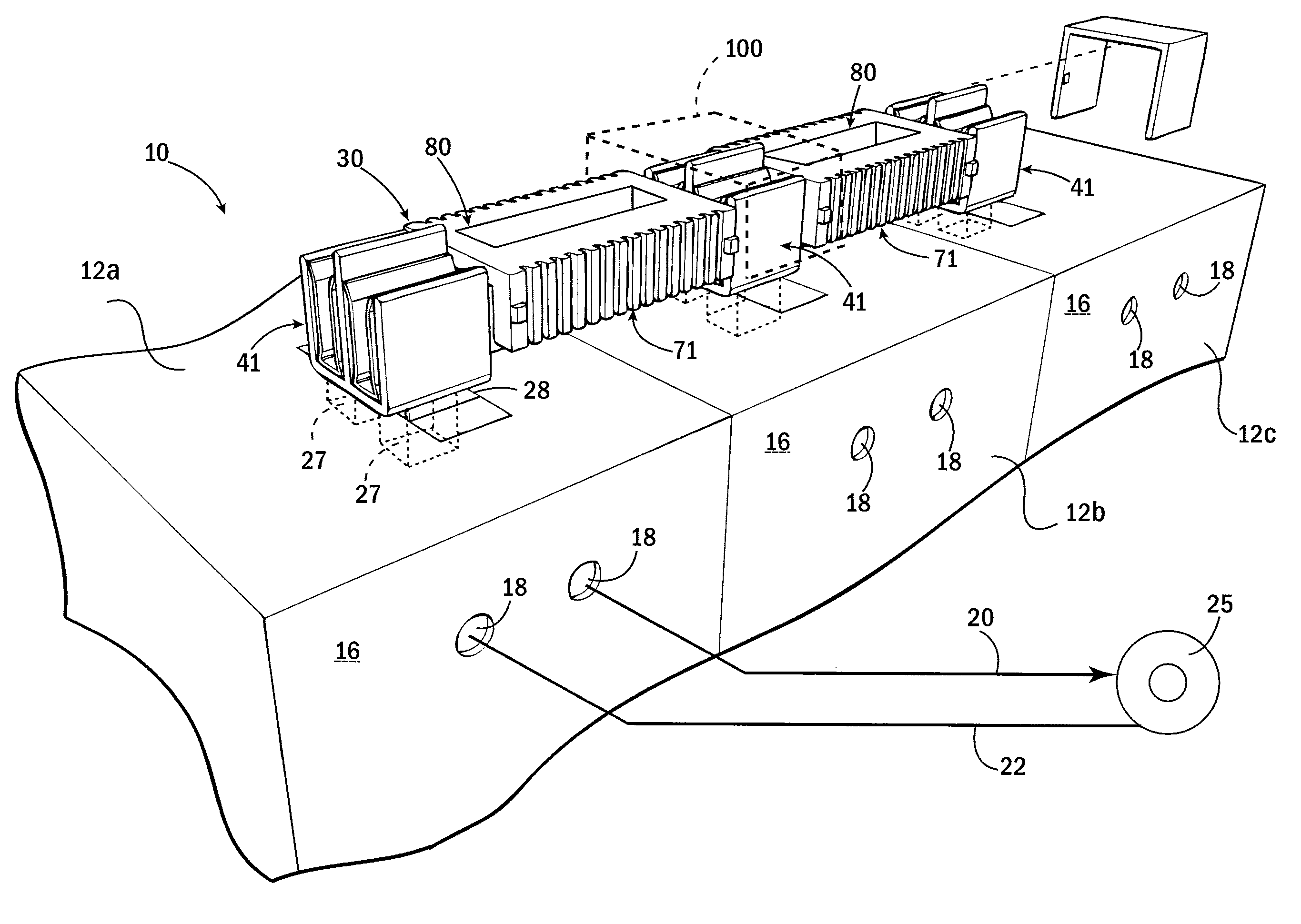
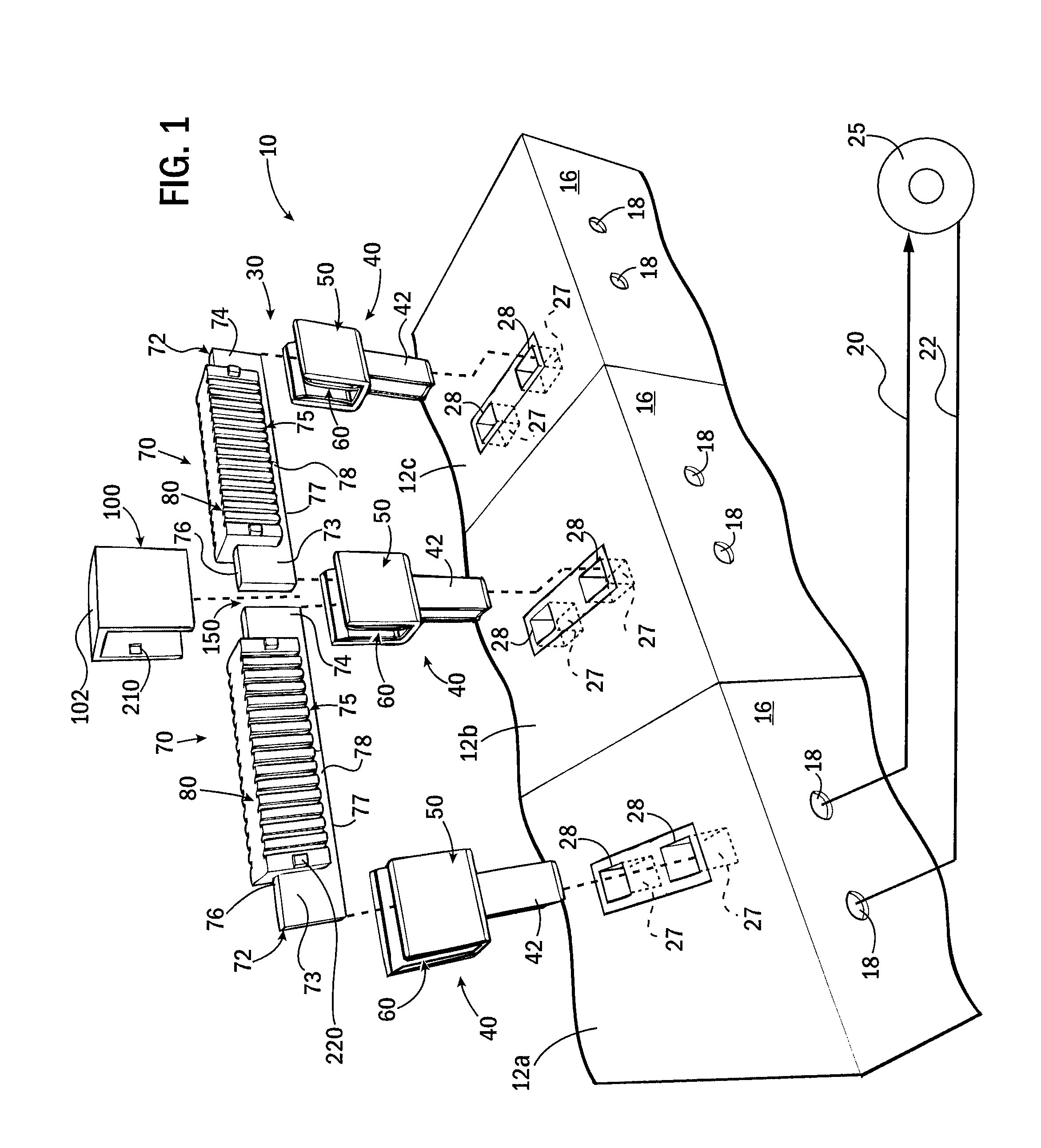
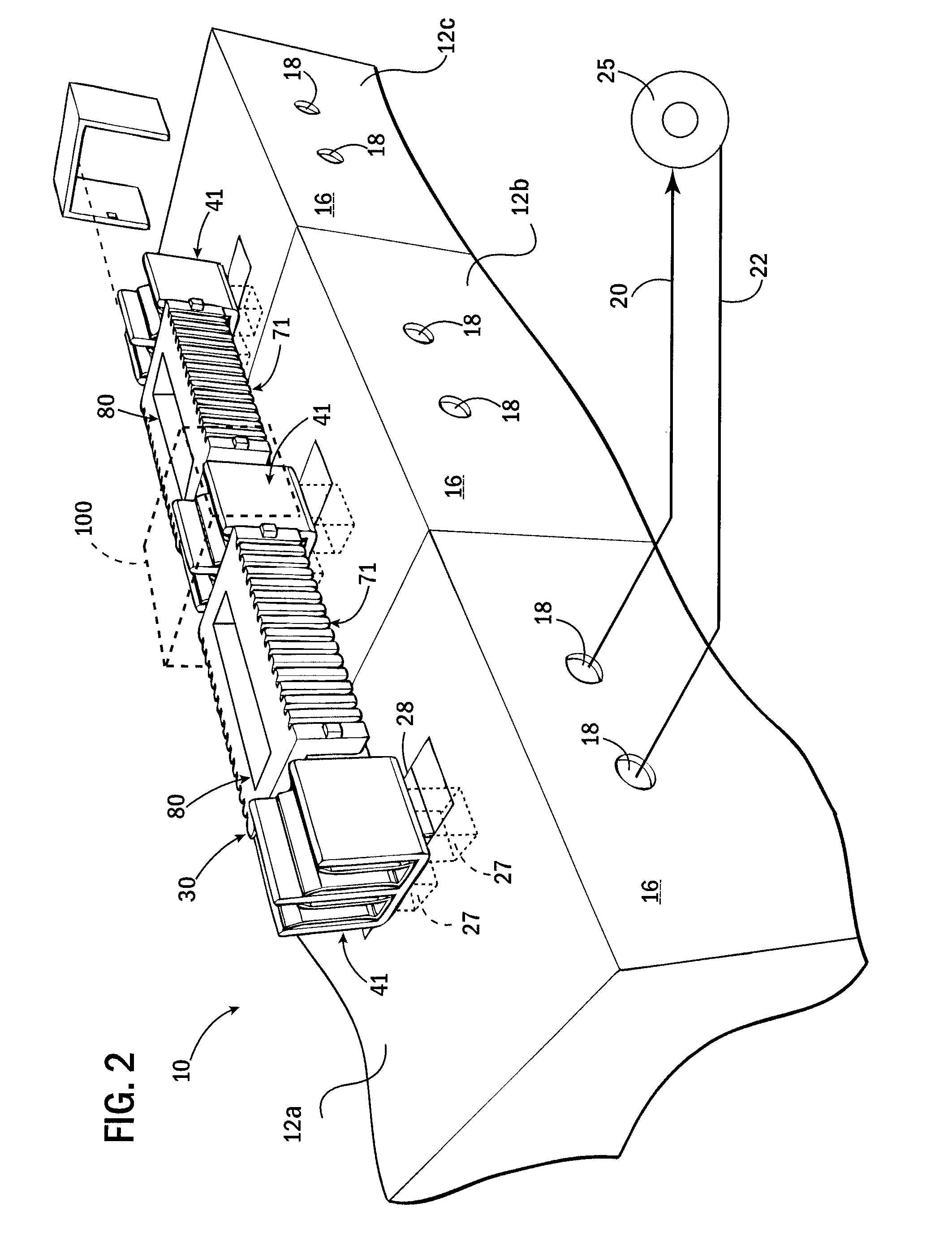
[0022]Referring now to FIGS. 1 and 2, a bus bar connector system 30 is a modular system that electronically connects at least two, while allowing for connecting an arbitrary number of, electronic components to each other in a tool-less manner. The bus bar connector system 30 is described as being used in a servo motor drive system 10 to simplify its explanation, while noting that the bus bar connector system 30 in other embodiments may be implemented to interconnect various other electronic components to each other.

[0023]Still referring to FIGS. 1 and 2, a servo motor drive system 10 may provide for multiple drive modules 12a-12c each having generally rectangular housings 14 that may be mounted in a control cabinet or the like to be in side-by-side adjacent relationship with respect to each other. Rear vertical walls 16 of the housings 14 may include openings through which connectors 18 are accessible and to which power conductors 20 and signal conductors 22 may be connected. Power ...


PUM


Abstract

A system for connecting motor drives to each other is disclosed that does not require the use of wire or tools. The system includes an adapter plug and bus bar modules that connect to each other at a conductive receptacle of the adapter plug to define a splice joint at the point of connect of the bus bar modules. The bus bar modules may include insulating covers and insulating clips may overlie the splice joints so that the system is substantially devoid of exposed surfaces of its conductive materials.

Description

CROSS-REFERENCE TO RELATED APPLICATIONS[0001]This application claims priority to U.S. Provisional Application No. 61 / 476,076 filed Apr. 15, 2011, the entire contents of which are incorporated herein by reference.BACKGROUND OF THE INVENTION[0002]The subject matter disclosed herein relates to electrical conductors that connect electronic components to each other and, more particularly, to wiring systems for connecting servo motor drives to each other within servo motor drive systems.[0003]Servomotors provide a motor coupled to a sensor, for example, a position sensor such as an encoder, so that feedback control of the motor may be provided, for example, precise positioning control. Typically, a servo motor drive system provides a servo motor, for example, a DC permanent magnet motor and position encoder, which is wired to a servo drive. The servo drive provides a controllable source of DC power as controlled by a feedback signal from the position encoder by, for example, using a PID (...

Claims


Application Information

Patent Timeline
Patent Type & Authority Patents(United States)
IPC IPC(8): H01R13/64
CPCH01R13/514H01R31/085H01R13/44H01R9/2675H02B13/005H02G5/10H01R9/2458H01R13/5213
Inventor BALCERAK, JOHN A.VAN GROLL, THOMAS H.WINTERHALTER, CRAIG R.
Owner ROCKWELL AUTOMATION TECH
Why Eureka
Try Eureka