Methods and apparatus for sputtering

a sputtering and apparatus technology, applied in the field of sputtering with, can solve the problems of low sputtering efficiency and lack of uniformity, and achieve the effect of enhancing the uniformity of deposition on the substra

Active Publication Date: 2013-11-19
AVIZA TECHNOLOGY INC
View PDF7 Cites 17 Cited by
  • Summary
  • Abstract
  • Description
  • Claims
  • Application Information

AI Technical Summary

Benefits of technology

[0010]From one aspect the invention consists in a method of sputtering with a sputtering apparatus having a sputter target and a magnetron for providing a field which moves relative to the target including controlling the speed of movement of the field such that the uniformity of deposition on the substrate is enhanced.
[0011]As will be demonstrated below, the Applicants have determined that, surprisingly, the rate at which the field passes across the target face affects the level of uniformity of deposition upon a substrate facing the target. Even more surprisingly, they have determined that a minimum in non-uniformity can be readily determined and better uniformity can be achieved by controlling the speed of rotation to that which produces a minimum. Put another way the speed can be selected to maximise the speed-enhanced uniformity.

Problems solved by technology

One of the key elements to achieve good uniformity of deposition upon a substrate from a closely spaced magnetron sputtering target assembly is the way in which the magnetic field moves with respect to the substrate (the alternative being large source-to-substrate distances approximating to a point source, but at the cost of low sputtering efficiency).
Whilst good results have been achieved using these techniques, and other techniques developed by the Applicants, lack of uniformity has still proved a significant problem in reactive sputtering processes.

Method used


Image

  • Methods and apparatus for sputtering
  • Methods and apparatus for sputtering
  • Methods and apparatus for sputtering

Examples


Embodiment Construction

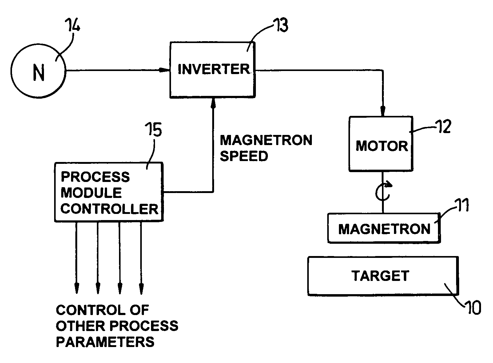
[0030]Referring first to FIG. 7, as is well-known, sputtering apparatus may include a target 10 having a rotatable magnetron 11 on its non-sputtering side. The magnetron may be rotated by a motor 12 or by other means such as a flow of cooling water impinging on an impeller.

[0031]In an embodiment of the inventive apparatus, an inverter 13 is supplied between the motor 12 and the supply 14 to allow control of the rotational speed of the motor 12.

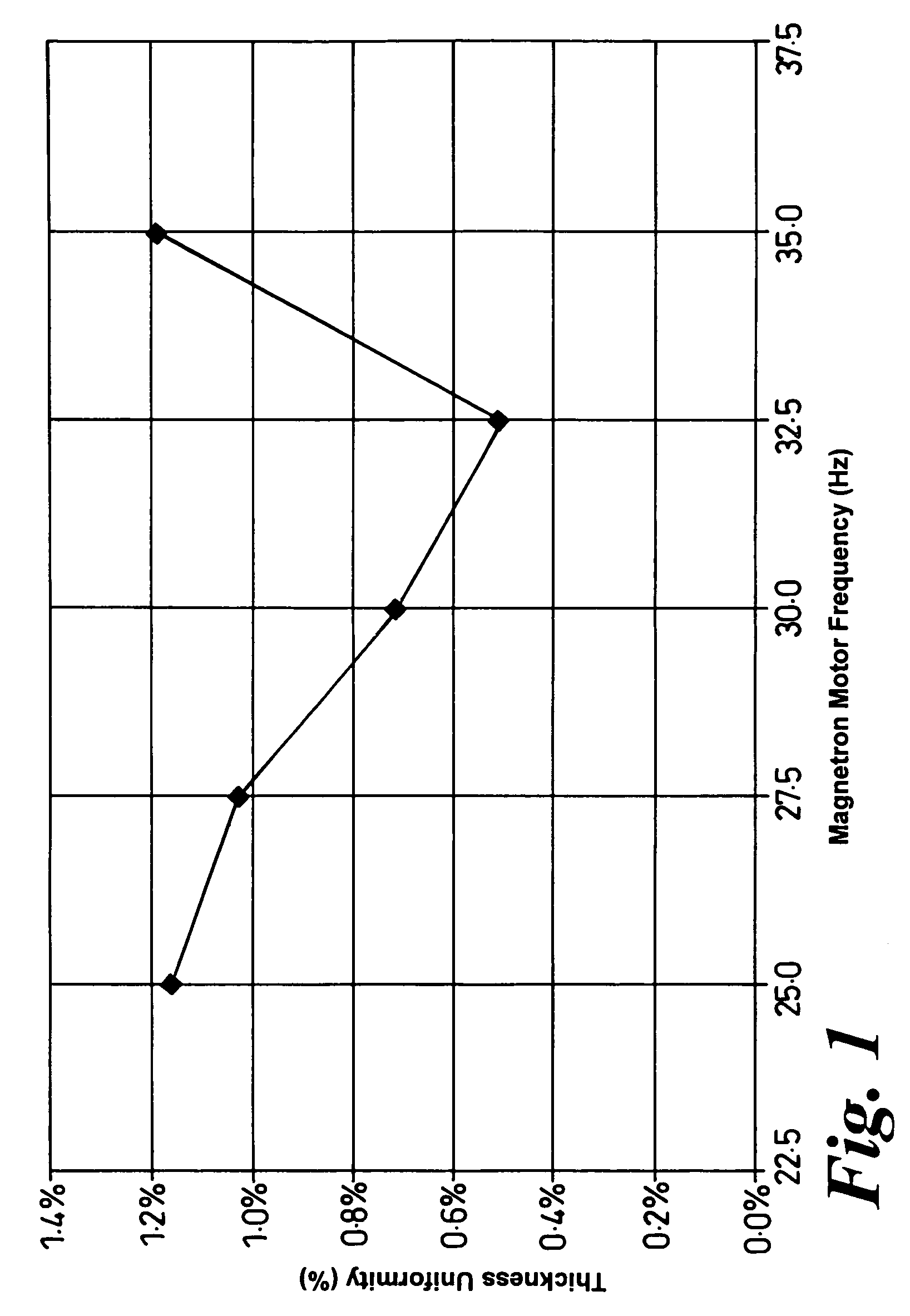
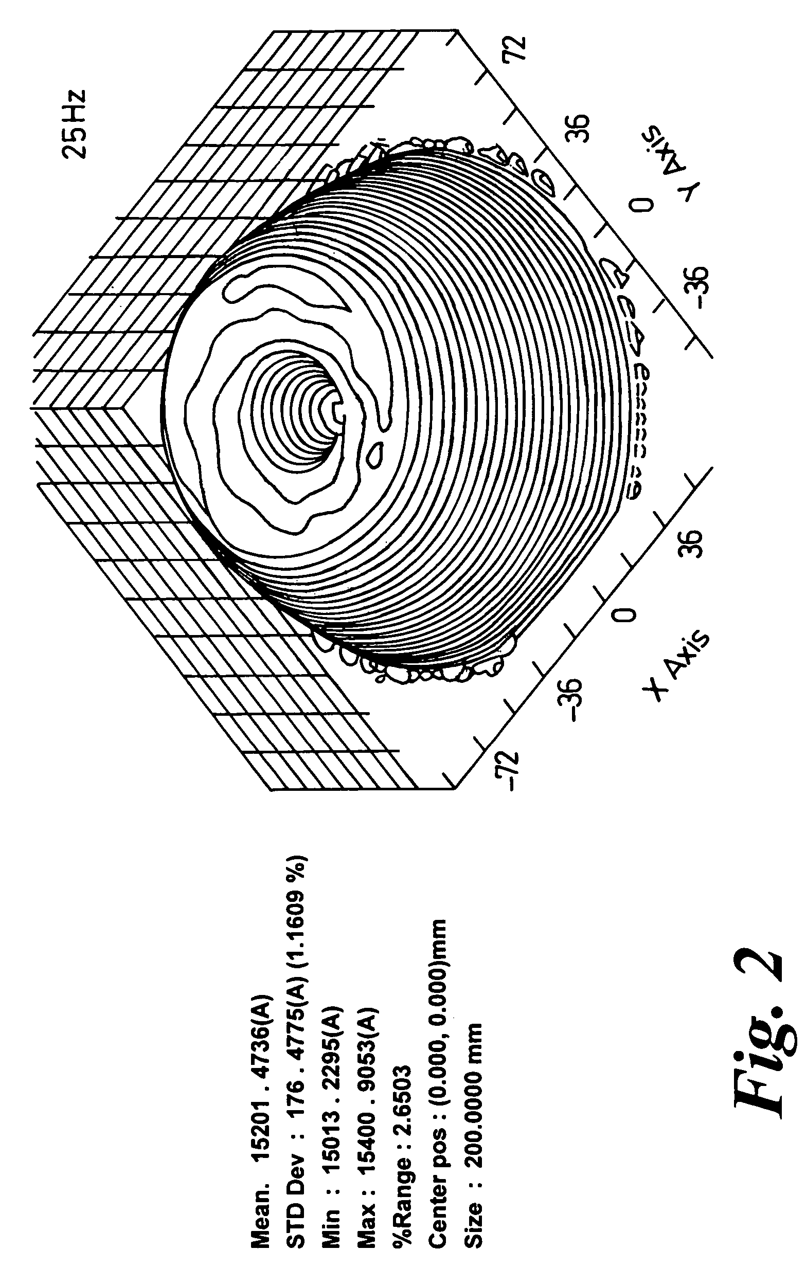
[0032]Using such apparatus the Applicants have processed a wafer under the following process conditions:[0033]200 mm Wafer[0034]target—aluminium[0035]45 mm target to wafer spacing[0036]Ar Gas Flow: 10 sccm[0037]N2 Gas Flow: 50 sccm[0038]Process pressure 2.2 millitorr[0039]Platen Temperature: 400° C., no wafer clamping[0040]Pulsed DC Target Power: 6 kW, Pulse frequency−100 kHz, Pulse width+4 μs[0041]Platen Bias Power: 130 W of 13.56 MHz

[0042]By using the inverter 13 to change the frequency of the supply to the magnetron motor 12, the speed of r...


PUM

PropertyMeasurementUnit
frequencyaaaaaaaaaa
frequencyaaaaaaaaaa
thicknessaaaaaaaaaa

Abstract

A method of sputtering with sputtering apparatus is for depositing a layer upon a substrate. The apparatus includes a sputter target with a face exposed to the substrate and a magnetron providing a magnetic field that moves relative to the target face. The speed of movement of the field is controlled such that the uniformity of the deposition on the substrate is enhanced. A particular method includes monitoring uniformity verses speed, selecting the speed that gives the preferred uniformity and controlling the field to the selected speed. The selected speed may vary over the life of the target, with increased speeds becoming desirable as the target thins.

Description

CROSS REFERENCE TO RELATED APPLICATION[0001]A claim to priority is made to U.S. Provisional Application Ser. No. 60 / 619712 filed Oct. 19, 2004 and British Patent Application No. 0423032.2 filed Oct. 16, 2004.BACKGROUND OF THE INVENTION[0002]1. Field of Invention[0003]This invention relates to a method of sputtering with a sputtering apparatus for depositing a layer upon a substrate having a sputter target with a face exposed to substrate(s) and a magnetron providing a magnetic field that moves relative to the target face.[0004]2. Description of Related Art[0005]In most deposition processes that take place, for example in the formation of films on semiconductor wafers, one of the key manufacturing criteria is that there should be uniformity of deposited film thickness across the wafer. In particular for acoustic resonators, film thickness affects resonant frequency and therefore for all resonators upon a wafer to resonate at the same frequency, film thickness must be the same.[0006]O...

Claims


Application Information

Patent Timeline
Patent Type & Authority Patents(United States)
IPC IPC(8): C23C14/00C23C14/32C25B9/00C25B11/00C25B13/00
CPCC23C14/35H01J37/3405H01J37/3455
Inventor FORD, MARK ASHLEYJAKKARAJU, RAJKUMAR
Owner AVIZA TECHNOLOGY INC
Why Eureka
Try Eureka