Electric joint design to be used in electromagnetic coils made with high-temperature superconducting tape, aspected wire, or cable

a technology of electric joints and electromagnetic coils, applied in the direction of superconductors/hyperconductors, superconducting magnets/coils, magnetic bodies, etc., can solve the problems of inapplicability of engineering approaches normally applied to round wires, degradation of electrical transport properties of conductors, and inability to easily bend tape conductors to change directions. , to achieve the effect of small heat loss and low contact resistan

Active Publication Date: 2013-11-19
FLORIDA STATE UNIV RES FOUND INC
View PDF2 Cites 6 Cited by
  • Summary
  • Abstract
  • Description
  • Claims
  • Application Information

AI Technical Summary

Benefits of technology

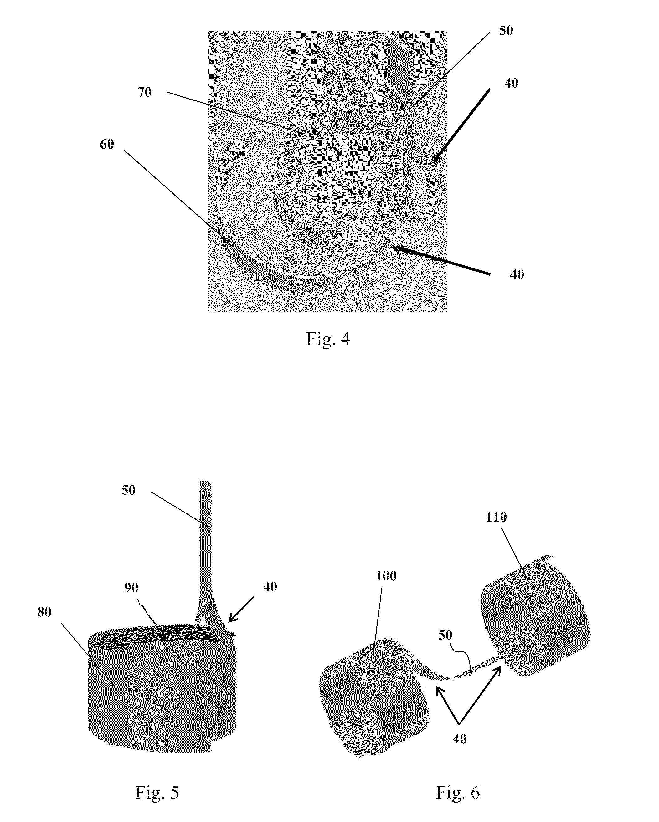
[0011]One embodiment of this invention involves soldering of a high-temperature superconductor onto a complex twist-bend contour in a terminal member. The conductor may be a high-temperature superconducting tape, aspected wire, or cable. The terminal member is made of an electrically conductive material, such as high purity copper. The twist-bend contour allows for a change in the conductor direction by about 90 degrees as the conductor leaves the helical section of the coil. This change in direction is achieved through a soft-bend and an internal twist without cutting the conductor or forcing a hard-bend into it. After the twist-soft-bend section of the contour, the conductor is aligned with the elec

Problems solved by technology

For technological reasons, HTS materials are commonly manufactured as tape, and therefore, engineering approaches normally applied to round wires are inapplicable to HTS tape.
Due to the geometrical and mechanical constraints, tape conductors cannot be easily bent to change direction when entering and exiting the coil section at some pre-determined winding pitch angle.
For this reason, hard-bends result in degradation of the electrical transport properties of the conductor and, therefore, are undesirable.
Since currently no technology exists that allows for making of superconducting joints with HTS materials, all electrical joints are resistive and cont

Method used


Image

  • Electric joint design to be used in electromagnetic coils made with high-temperature superconducting tape, aspected wire, or cable
  • Electric joint design to be used in electromagnetic coils made with high-temperature superconducting tape, aspected wire, or cable
  • Electric joint design to be used in electromagnetic coils made with high-temperature superconducting tape, aspected wire, or cable

Examples


Embodiment Construction

[0019]The claimed invention solves the problem associated with heat generating resistive joints in high temperature superconductor coil terminals used in high field magnets.

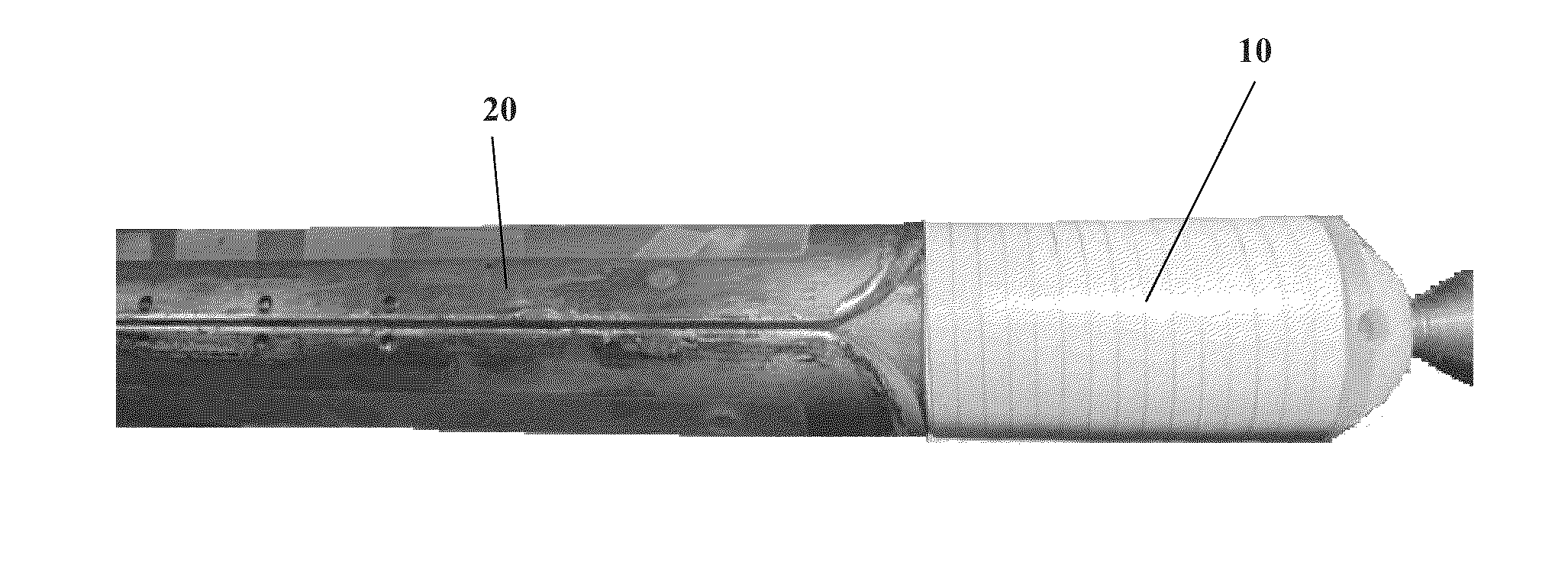
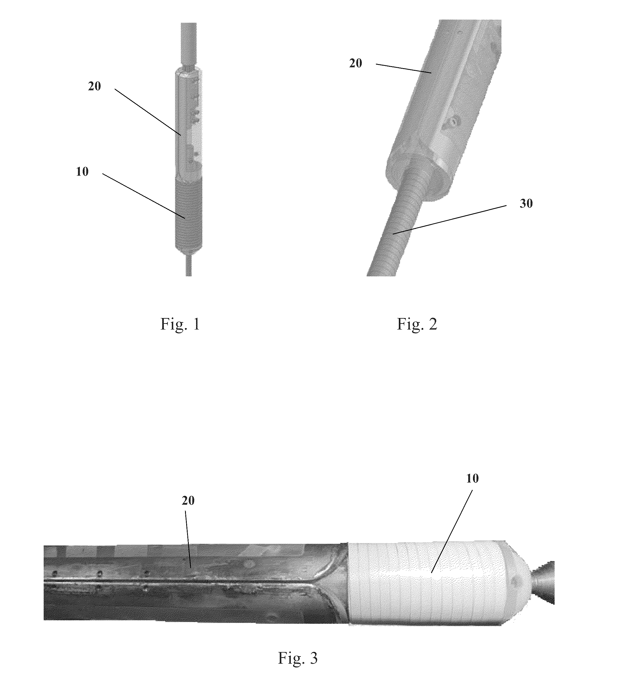
[0020]Referring to FIGS. 1-2, one embodiment of the claimed invention involves a coil having an outer layer 10 and an inner layer 30. The coil is made of a high-temperature superconductor (HTS), which may be in a form of a tape, aspected wire, or cable. One type of HTS material contemplated by the invention is Rare Earth Barium Cuprates (REBCO) coated tape. Outer coil layer 10 has a helical section depicted in FIGS. 1 and 3, and a terminal section 60 depicted in FIG. 4; inner coil layer 30 has a helical section, which is depicted in FIG. 2, and a terminal section 70, which is depicted in FIG. 4.

[0021]FIGS. 1-3 depict a terminal member 20, which is made of an electrically conductive material, such as high purity copper. Terminal member 20 contains a complex bend-twist contour 40, which is depicted in FIG. 4. Conto...


PUM


Abstract

An electric joint design to be used in electromagnetic coils made with high-temperature superconducting tape, aspected wire, or cable. A terminal member contains an engraved twist-bend contour, which receives the coil and changes the direction of the coil by about 90 degrees without any hard-bends. A current lead is aligned with terminal section of the coil establishing an electric joint whose length is not limited by the coil geometry. Resistance is distributed along the length of the electric joint to reduce heat generation. The electric joint is placed away from the area where the magnetic forces are high to eliminate the problem of helium gas becoming trapped.

Description

CROSS REFERENCE TO RELATED APPLICATION[0001]This application claims priority to U.S. Provisional Patent Application No. 61 / 451,254, entitled “Electric Joint Design to be Used in Electromagnetic Coils Made With High-Temperature Superconducting Tape”, filed on Mar. 10, 2011, the contents of which are herein incorporated by reference.GOVERNMENT SUPPORT[0002]This invention was made with government support under grant No. 0923070 awarded by the National Science Foundation. The government has certain rights in the invention.FIELD OF THE INVENTION[0003]This invention relates to an electric joint design. More specifically, the invention relates to an electric joint design to be used in electromagnetic coils made with high-temperature superconducting tape, aspected wire, or cable for high field magnets.BACKGROUND OF THE INVENTION[0004]High-temperature superconductors (HTS) have been developed by research institutions and industry, and substantial efforts are currently being made to commercia...

Claims


Application Information

Patent Timeline
IPC IPC(8): H01L39/24H01B12/00
CPCH01F6/065H02G15/34Y02E40/648Y02E40/60
Inventor TROCIEWITZ, ULF PETERHILTON, DAVID K.VIOUCHKOV, YOURIDALBAN-CANASSY, MATTHIEU
Owner FLORIDA STATE UNIV RES FOUND INC
Why Eureka
Try Eureka