Carbon-free fire tube boiler

a fire tube boiler and carbon-free technology, applied in the field of energy generation, can solve the problem that fire tube boilers typically produce large quantities of exhaus

Inactive Publication Date: 2013-11-26
KING FAHD UNIVERSITY OF PETROLEUM AND MINERALS
View PDF33 Cites 9 Cited by
  • Summary
  • Abstract
  • Description
  • Claims
  • Application Information

AI Technical Summary

Problems solved by technology

However, despite their myriad uses, fire tube boilers typically produce great quantities of exhaust, particularly due to their primary reliance upon the combustion of fossil fuels.

Method used


Image

  • Carbon-free fire tube boiler
  • Carbon-free fire tube boiler
  • Carbon-free fire tube boiler

Examples


Embodiment Construction

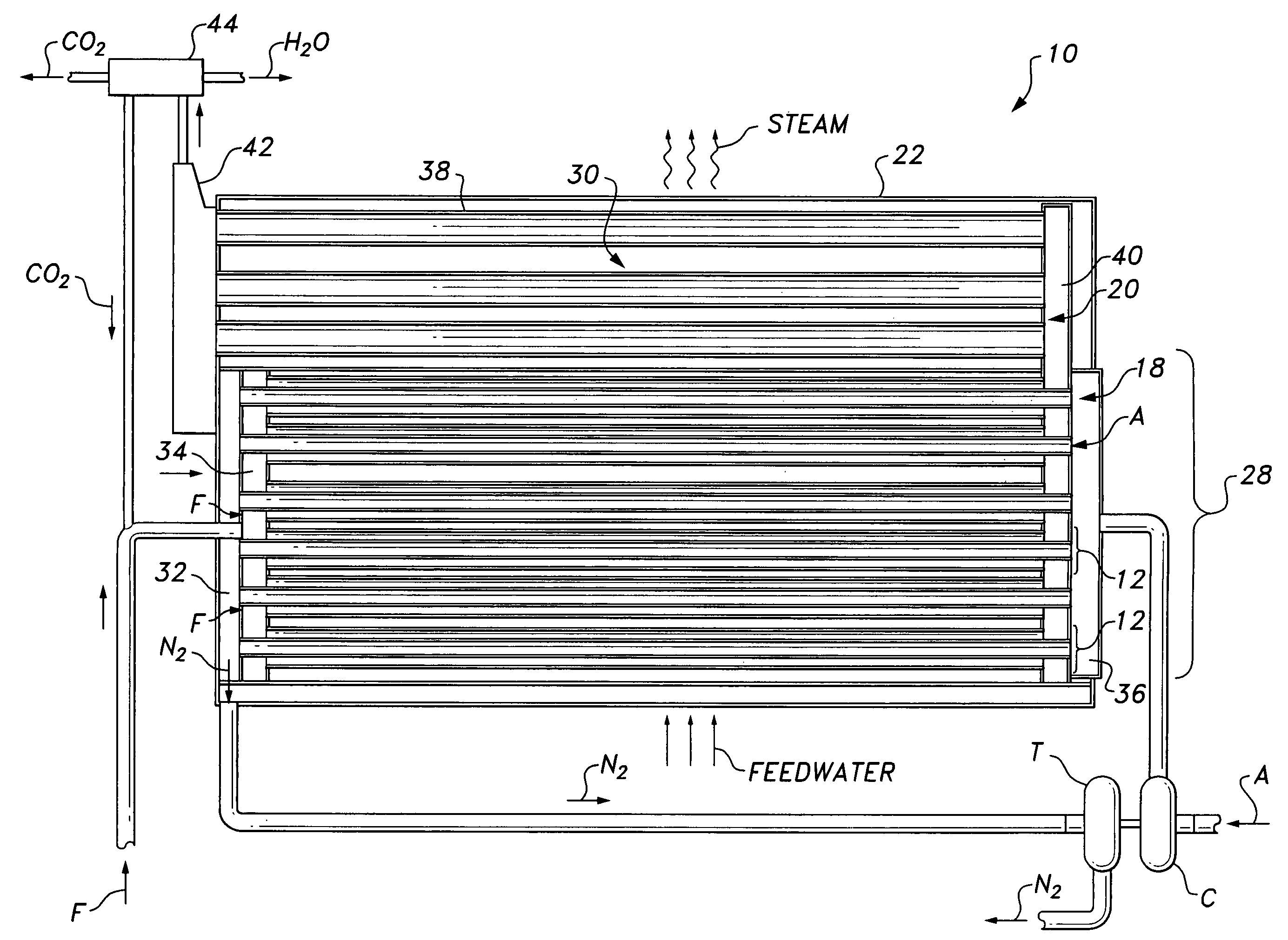
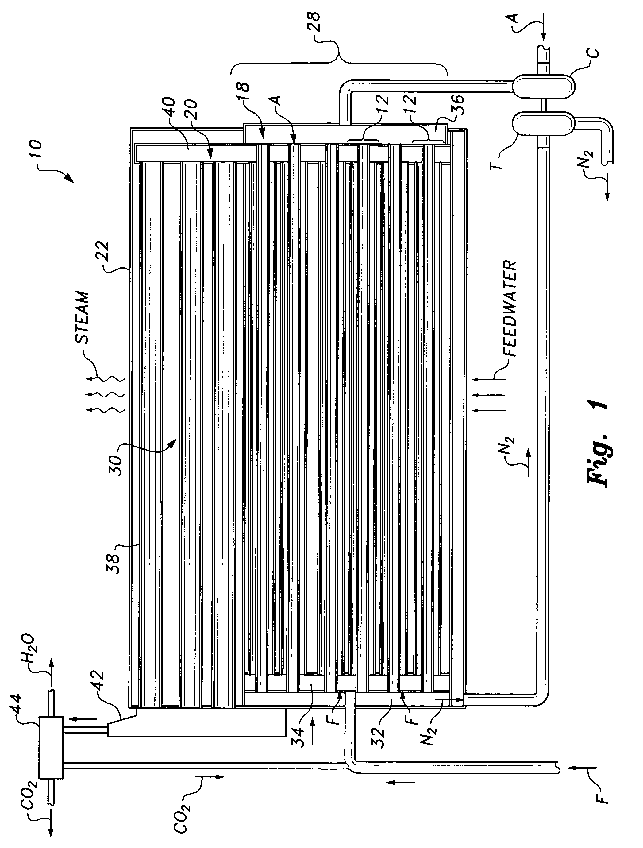
[0018]FIGS. 1 and 3 diagrammatically illustrate the carbon-free fire tube boiler 10. As best shown in FIG. 1, housing 22 contains a first stage 18 and a second stage 20. As will be described in detail below, within first stage 18, fuel F, which may be natural gas or any other type of hydrocarbon fuel combustible with oxygen, is combusted with oxygen gas (denoted hereinafter as O2) obtained from environmental air A, resulting in gaseous carbon dioxide (denoted hereinafter as CO2) and water vapor (denoted hereinafter as H2O).

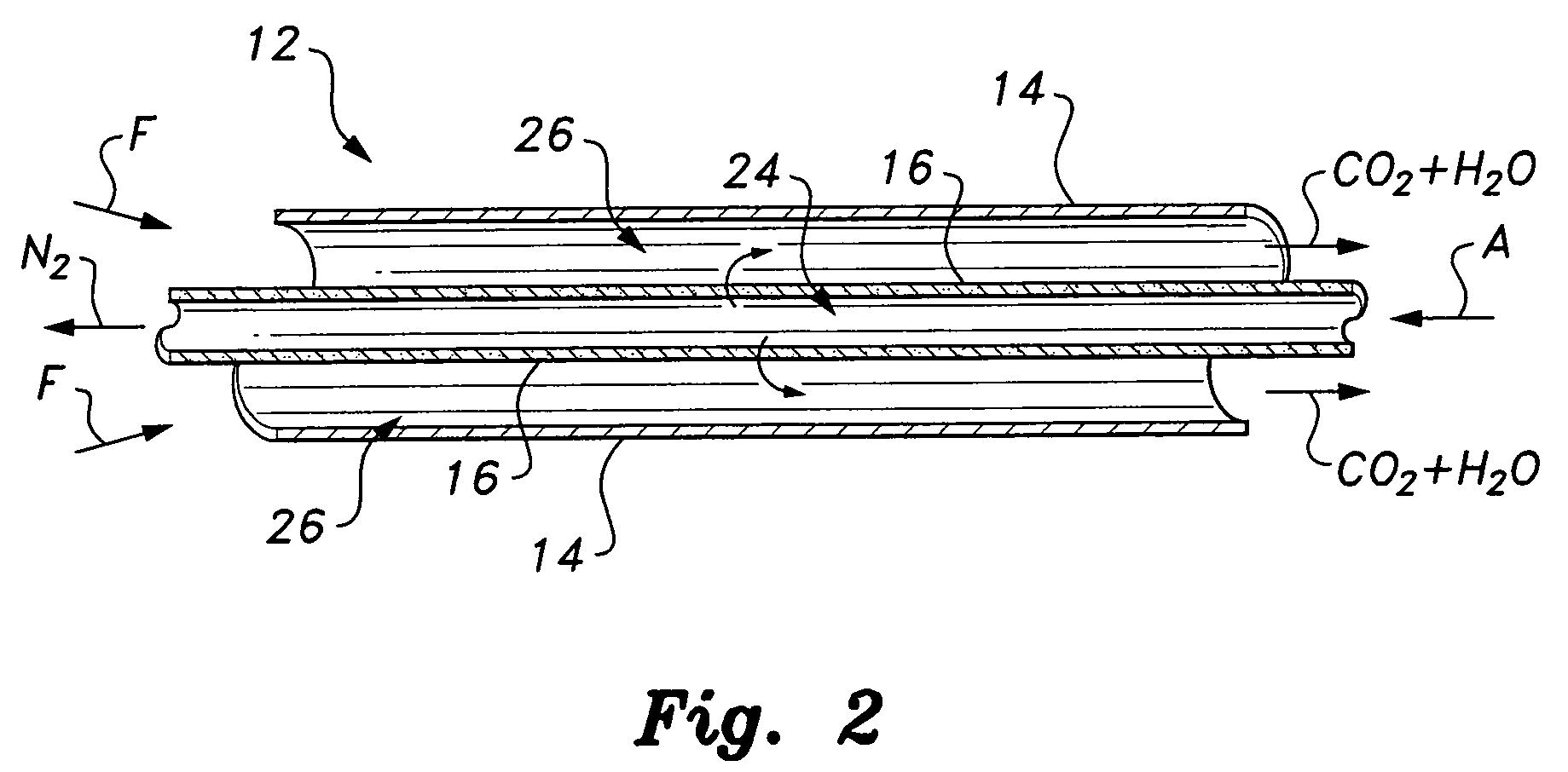
[0019]First stage 18 includes a plurality 28 of oxygen transport reactors (OTRs) 12. As shown in FIGS. 2 and 3, each OTR 12 is preferably cylindrical, including an outer cylindrical wall 14 with an inner cylindrical ion transport membrane 16 positioned coaxially therein. Each OTR 12 in the first stage group 28 is surrounded by water within water reservoir 30. Heat transfer occurs from each OTR to the water W. As shown in FIGS. 1 and 2, environmental air A is pumpe...


PUM


Abstract

The carbon-free fire tube boiler is a boiler for heating water by combustion of hydrocarbon fuels with oxygen. The boiler includes a housing defining first and second heat transfer stages. At least one oxygen transport reactor is received within the first heat transfer stage. The oxygen transport reactor includes an outer wall and an inner cylindrical ion transport membrane. The membrane receives pressurized air and separates gaseous oxygen therefrom, transporting the oxygen into an annular region between the membrane and the outer wall. The gaseous hydrocarbon fuel is delivered into the annular region for combustion, producing gaseous carbon dioxide and water vapor. A water reservoir is defined within the first and second stages, with the at least one oxygen transport reactor and at least one transfer tube passing therethrough. The carbon dioxide and the water vapor are delivered through the at least one transfer tube for heating water contained therein.

Description

BACKGROUND OF THE INVENTION[0001]1. Field of the Invention[0002]The present invention relates generally to energy generation, and particularly to a carbon-free fire tube boiler that minimizes carbon dioxide exhaust into the environment.[0003]2. Description of the Related Art[0004]A boiler is a closed vessel in which water or other fluid is heated. The heated or vaporized fluid exits the boiler for use in various processes or heating applications. A fire tube boiler is a type of boiler in which hot gases from a fire pass through one or more tubes running through a sealed container of water. The heat energy from the gases passes through the sides of the tubes by thermal conduction, convection and radiative heat transfer, heating the water and ultimately creating steam.[0005]Fire tube boilers are well known, particularly since steam locomotives used fire tube boilers as their source of propulsion. In the locomotive-type boiler, fuel is burned in a firebox to produce hot combustion gase...

Claims


Application Information

Patent Timeline
Patent Type & Authority Patents(United States)
IPC IPC(8): F22B13/04
CPCF22B1/18F22B9/10F23D14/22F23D14/32F23L7/007Y02E20/344Y02E20/34
Inventor HABIB, MOHAMED ABDEL-AZIZBEN-MANSOUR, RACHED
Owner KING FAHD UNIVERSITY OF PETROLEUM AND MINERALS
Why Eureka
Try Eureka