Arrangement in a low-temperature cooling system for a supercharged combustion engine

a combustion engine and low-temperature cooling technology, which is applied in the direction of machines/engines, mechanical equipment, non-fuel substance addition to fuel, etc., can solve the problems of water freezing to ice within the cooler, and the risk is greater, so as to eliminate the risk of the cooler being obstructed and good cooling

Inactive Publication Date: 2013-11-26
SCANIA CV AB
View PDF15 Cites 2 Cited by
  • Summary
  • Abstract
  • Description
  • Claims
  • Application Information

AI Technical Summary

Benefits of technology

[0005]The object of the present invention is to provide an arrangement whereby a gaseous medium which contains water vapour can be subjected to very good cooling in a cooler while at the same time the risk of the cooler being obstructed is eliminated.
[0008]According to another preferred embodiment of the invention, the control unit is adapted to controlling the coolant pump so that it again circulates a normal flow of coolant through the cooler when it receives a parameter value which exceeds an upper threshold value. When the coolant pump is switched off or circulates a reduced flow through the cooler, the gaseous medium undergoes reduced cooling in the cooler. The gaseous medium leaving the cooler will therefore be at a progressively rising temperature. When the temperature of the medium has risen to the upper threshold value, the control unit will find that the risk of ice formation is at least temporarily over, after which it will restart the coolant pump. The coolant pump is with advantage powered electrically. Such a coolant pump can easily be switched on and off.

Problems solved by technology

If the coolant is also colder than 0° C., there is obvious risk of the water freezing to ice within the cooler.
The lower the temperature of the coolant in the low-temperature cooling system, the greater this risk.

Method used


Image

  • Arrangement in a low-temperature cooling system for a supercharged combustion engine
  • Arrangement in a low-temperature cooling system for a supercharged combustion engine
  • Arrangement in a low-temperature cooling system for a supercharged combustion engine

Examples


Embodiment Construction

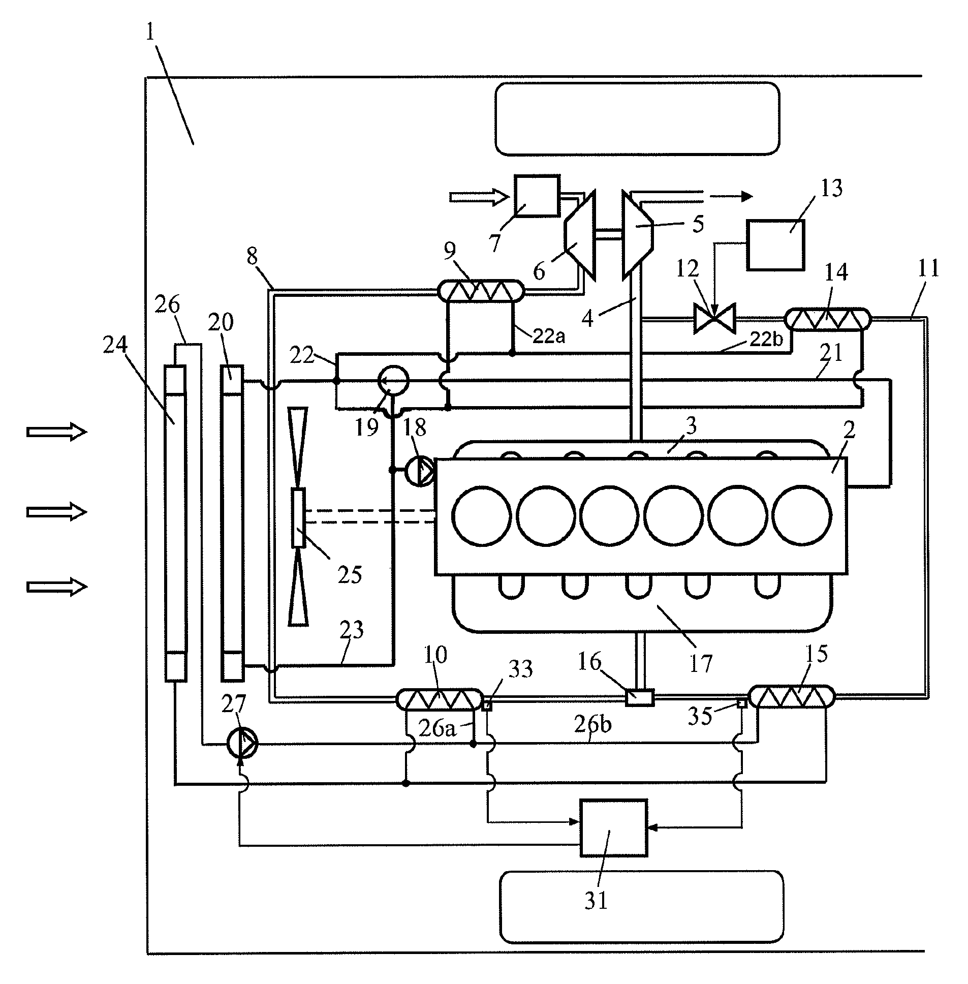
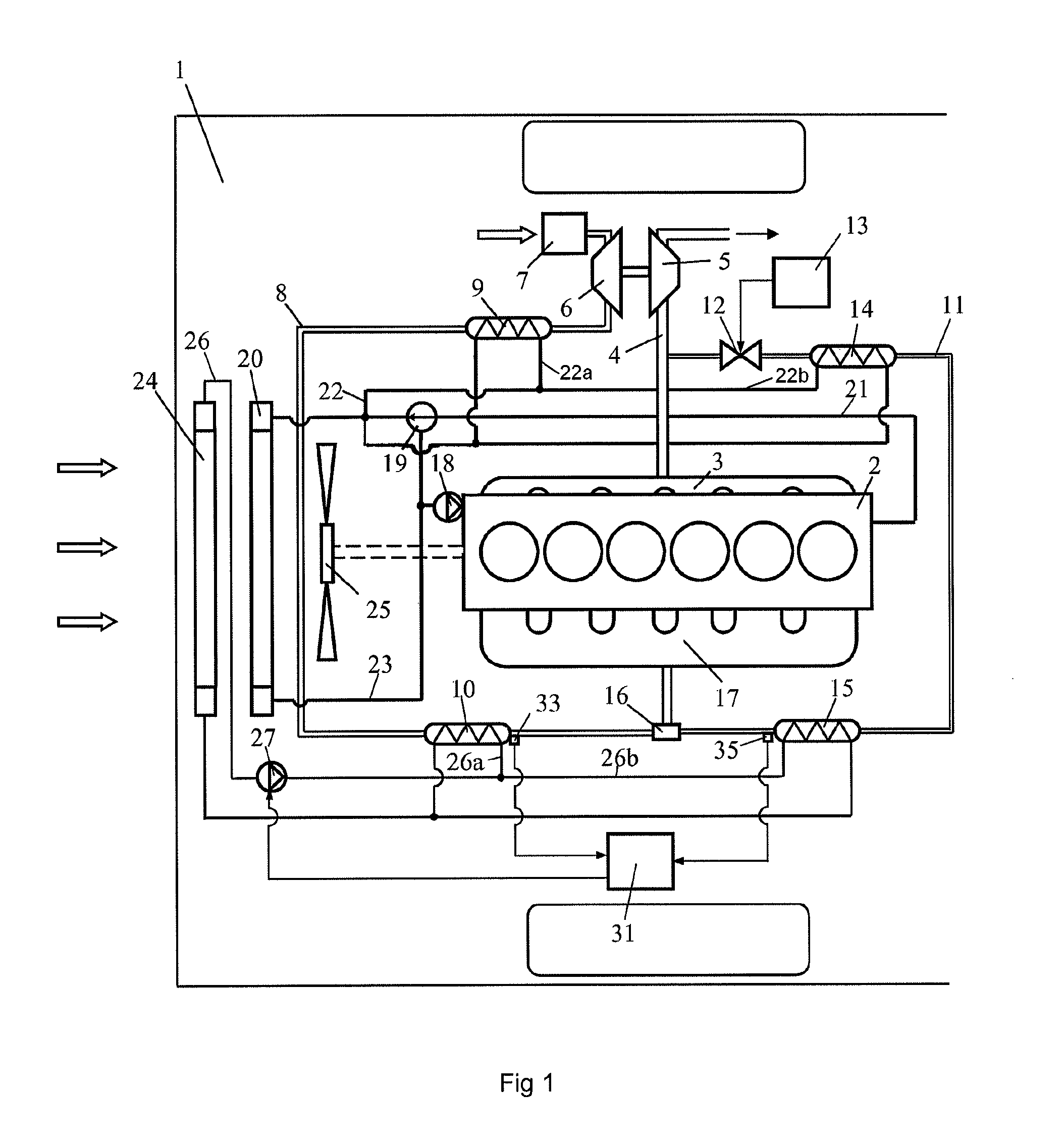
[0015]FIG. 1 depicts an arrangement for a supercharged combustion engine which is intended to power a schematically depicted vehicle 1. The combustion engine is here exemplified as a diesel engine 2. The diesel engine 2 may be intended to power a heavy vehicle 1. The exhaust gases from the cylinders of the diesel engine 2 are led via an exhaust manifold 3 to an exhaust line 4. The diesel engine 2 is provided with a turbo unit which comprises a turbine 5 and a compressor 6. The exhaust gases in the exhaust line 4, which are at above atmospheric pressure, are led initially to the turbine 5. The turbine 5 is thus provided with driving power which is transferred, via a connection, to the compressor 6. The compressor 6 uses this power to compress air which is drawn into an air inlet line 8 via an air filter 7. The air in the inlet line is cooled initially in a first coolant-cooled charge air cooler 9. The air is cooled in the first charge air cooler 9 by coolant from the combustion engin...


PUM


Abstract

An arrangement for controlling cooling of a gas for a supercharged combustion engine includes a low temperature cooling system with a coolant, a coolant pump circulating the coolant in the cooling system, a cooler in which a gas containing water vapor is cooled by the coolant, at least one sensor for detecting a parameter indicating whether the gas is cooled so much that there is at least risk of ice formation in the cooler, and a control unit receiving information from the sensors and deciding whether there is at least risk of ice formation in the cooler and, if so, controlling the coolant pump to be temporarily switched off or to circulate a lower than normal flow of coolant through the cooler.

Description

CROSS-REFERENCE TO RELATED APPLICATIONS[0001]The present application is a 35 U.S.C. §§371 national phase conversion of PCT / SE2009 / 051017, filed Sep. 14, 2009 which claims priority of Swedish Application No. 0802031-5, filed Sep. 25, 2008, the contents of which are incorporated by reference herein. The PCT International Application was published in the English language.BACKGROUND TO THE INVENTION, AND STATE OF THE ART[0002]The present invention relates to an arrangement for cooling gases used for a supercharged combustion engine.[0003]The amount of air which can be supplied to a supercharged combustion engine depends on the pressure of the air but also on the temperature of the air. Supplying the largest possible amount of air to the combustion engine entails effective cooling of the air before it is led to the combustion engine. The air is usually cooled in a charge air cooler arranged at a front portion of a vehicle. At that location the charge air cooler has a cooling air flow at ...

Claims


Application Information

Patent Timeline
Patent Type & Authority Patents(United States)
IPC IPC(8): F01P9/00F01P7/14F02B33/44
CPCF01P3/12F01P7/162F01P7/164F02B29/0412F02B29/0443F02M25/0732F01P2060/02Y02T10/121Y02T10/146F02M26/24Y02T10/12F01P7/165F01P11/16F02B29/0493F02M26/28
Inventor KARDOS, ZOLTANSODERBERG, ERIK
Owner SCANIA CV AB
Why Eureka
Try Eureka